Module 10 - Introduction to Wave Propagation, Transmission Lines, and Antennas
Pages i,
1-1,
1-11,
1-21,
1-31,
1-41,
2-1,
2-11,
2-21,
2-31,
2-40,
3-1,
3-11,
3-21,
3-31,
3-41,
3-51,
4-1,
4-11,
4-21,
4-31,
4-41,
4-51, Index
SPORADIC E. - Irregular
cloud-like patches of unusually high ionization, called sporadic E, often form at heights near the normal E layer.
Exactly what causes this phenomenon is not known, nor can its occurrence be predicted. It is known to vary
significantly with latitude, and in the northern latitudes, it appears to be closely related to the aurora
borealis or northern lights. At times the sporadic E is so thin that radio waves penetrate it easily and
are returned to earth by the upper layers. At other times, it extends up to several hundred miles and is heavily
ionized. These characteristics may be either harmful or helpful to radio wave propagation. For example,
sporadic E may blank out the use of higher, more favorable ionospheric layers or cause additional absorption of
the radio wave at some frequencies. Also, it can cause additional multipath problems and delay the arrival times
of the rays of RF energy.
On the other hand, the critical frequency of the sporadic E is very high and can be greater than double the
critical frequency of the normal ionospheric layers. This condition may permit the long distance transmission of
signals at unusually high frequencies. It may also permit short distance communications to locations that would
normally be in the skip zone. The sporadic E can form and disappear in a short time during either the day
or night. However, it usually does not occur at the same time at all transmitting or receiving stations.
SUDDEN IONOSPHERIC DIsTURBANCES. - The most startling of the ionospheric irregularities is known as
a SUDDEN IONOSPHERIC DIsTURBANCE (sid). These disturbances may occur without warning and may prevail for any
length of time, from a few minutes to several hours. When sid occurs, long distance propagation of HF radio waves
is almost totally "blanked out." The immediate effect is that radio operators listening on normal frequencies are
inclined to believe their receivers have gone dead. When sid has occurred, examination of the sun has
revealed a bright solar eruption. All stations lying wholly, or in part, on the sunward side of the Earth are
affected. The solar eruption produces an unusually intense burst of ultraviolet light, which is not absorbed by
the F2, F1, and E layers, but instead causes a sudden abnormal increase in the ionization density of the D layer.
As a result, frequencies above 1 or 2 megahertz are unable to penetrate the D layer and are usually completely
absorbed by the layer. IONOSPHERIC STORMS. - Ionospheric storms are disturbances in the
Earth's magnetic field. They are associated, in a manner not fully understood, with both solar eruptions and the
27-day intervals, thus corresponding to the rotation of the sun. Scientists believe that ionospheric
storms result from particle radiation from the sun. Particles radiated from a solar eruption have a slower
velocity than ultraviolet light waves produced by the eruption. This would account for the 18-hour or so time
difference between a sid and an ionospheric storm. An ionospheric storm that is associated with sunspot activity
may begin anytime from 2 days before an active sunspot crosses the central meridian of the sun until four days
after it passes the central meridian. At times, however, active sunspots have crossed the central region of the
sun without any ionospheric storms occurring. Conversely, ionospheric storms have occurred when there were no
visible spots on the sun and no preceding sid. As you can see, some correlation between ionospheric storms, sid,
and sunspot activity is possible, but there are no hard and fast rules. Ionospheric storms can occur suddenly
without warning. The most prominent effects of ionospheric storms are a turbulent ionosphere and very
erratic sky wave propagation. Critical frequencies are lower than normal, particularly for the F2 layer.
Ionospheric storms affect the higher F2 layer first, reducing its ion density. Lower layers are not appreciably
affected by the storms unless the disturbance is great. The practical effect of ionospheric storms is that the
range of
2-31
frequencies that can be used for communications on a given circuit is much smaller than normal, and
communications are possible only at the lower working frequencies. Q32. What are the two general types
of variations in the ionosphere? Q33. What is the main difference between these two types of variations?
Q34. What are the four main classes of regular variation which affect the extent of ionization in the
ionosphere? Q35. What are the three more common types of irregular variations in the ionosphere?
Frequency SELECTION Considerations Up to this point, we have covered various factors that control
the propagation of radio waves through the ionosphere, such as the structure of the ionosphere, the incidence
angle of radio waves, operating frequencies, etc. There is a very good reason for studying radio wave propagation.
You must have a thorough knowledge of radio wave propagation to exercise good judgment when you select
transmitting and receiving antennas and operating frequencies. Selection of a suitable operating frequency (within
the bounds of frequency allocations and availability) is of prime importance in maintaining reliable
communications.
For successful communications between any two specified locations at
any given time of the day, there is a maximum frequency,
a lowest frequency, and an optimum frequency that can be used.
Maximum Usable Frequency As we discussed earlier, the higher the frequency of a radio
wave, the lower the rate of refraction by an ionized layer. Therefore, for a given angle of incidence and time of
day, there is a maximum frequency that can be used for communications between two given locations. This frequency
is known as the Maximum USABLE Frequency (MUF). Waves at frequencies above the MUF are normally refracted
so slowly that they return to Earth beyond the desired location, or pass on through the ionosphere and are lost.
You should understand, however, that use of an established MUF certainly does not guarantee successful
communications between a transmitting site and a receiving site. Variations in the ionosphere may occur at any
time and consequently raise or lower the predetermined MUF. This is particularly true for radio waves being
refracted by the highly variable F2 layer. The MUF is highest around noon when ultraviolet light waves
from the sun are the most intense. It then drops rather sharply as recombination begins to take place.
Lowest Usable Frequency
As there is a maximum operating frequency that can be used for communications between two points, there is also a
minimum operating frequency. This is known as the LowEST USABLE Frequency (LUF). As the frequency of a
radio wave is lowered, the rate of refraction increases. So a wave whose frequency is below the established LUF is
refracted back to Earth at a shorter distance than desired, as shown in figure 2-23.
2-32

Figure 2-23. - Refraction of frequency below the lowest usable frequency (LUF). The transmission path that results from the rate of refraction is not the only factor that determines
the LUF. As a frequency is lowered, absorption of the radio wave increases. a wave whose frequency is too low is
absorbed to such an extent that it is too weak for reception. Likewise, atmospheric noise is greater at lower
frequencies; thus, a low-frequency radio wave may have an unacceptable signal-to-noise ratio. For a given
angle of incidence and set of ionospheric conditions, the LUF for successful communications between two locations
depends on the refraction properties of the ionosphere, absorption considerations, and the amount of atmospheric
noise present.
Optimum Working Frequency Neither the MUF nor the LUF is a practical operating frequency.
While radio waves at the LUF can be refracted back to Earth at the desired location, the signal-to-noise ratio is
still much lower than at the higher frequencies, and the probability of multipath propagation is much greater.
Operating at or near the MUF can result in frequent signal fading and dropouts when ionospheric variations alter
the length of the transmission path. The most practical operating frequency is one that you can rely on
with the least amount of problems. It should be high enough to avoid the problems of multipath, absorption, and
noise encountered at the lower frequencies; but not so high as to result in the adverse effects of rapid changes
in the ionosphere.
a frequency that meets the above criteria has been established and is known as the OPTIMUM Working Frequency. It
is abbreviated "FOT" from the initial letters of the French words for optimum working frequency, "frequence
optimum de travail." The FOT is roughly about 85 percent of the MUF but the actual percentage varies and may be
either considerably more or less than 85 percent. Q36. What do the letters MUF, LUF, and FOT stand for?
Q37. When is MUF at its highest and why? Q38. What happens to the radio wave if the LUF is too
low?
2-33
Q39. What are some disadvantages of operating transmitters at or near the LUF? Q40. What are some
disadvantages of operating a transmitter at or near the MUF? Q41. What is FOT?
WEATHER VERSUS PROPAGATION Weather is an additional factor that affects the
propagation of radio waves. In this section, we will explain how and to what extent the various weather phenomena
affect wave propagation. Wind, air temperature, and water content of the atmosphere can combine in many
ways. Certain combinations can cause radio signals to be heard hundreds of miles beyond the ordinary range of
radio communications. Conversely, a different combination of factors can cause such attenuation of the signal that
it may not be heard even over a normally satisfactory path. Unfortunately, there are no hard and fast rules on the
effects of weather on radio transmissions since the weather is extremely complex and subject to frequent change.
We will, therefore, limit our discussion on the effects of weather on radio waves to general terms.
PRECIPITATION ATTENUATION Calculating the effect of weather on radio wave propagation would be
comparatively simple if there were no water or water vapor in the atmosphere. However, some form of water (vapor,
liquid, or solid) is always present and must be considered in all calculations. Before we begin discussing the
specific effects that individual forms of precipitation (rain, snow, fog) have on radio waves, you should
understand that attenuation because of precipitation is generally proportionate to the frequency and wavelength of
the radio wave. For example, rain has a pronounced effect on waves at microwave frequencies. However, rain hardly
affects waves with long wavelengths (HF range and below). You can assume, then, that as the wavelength becomes
shorter with increases in frequency, precipitation has an increasingly important attenuation effect on radio
waves. Conversely, you can assume that as the wavelength becomes longer with decreases in frequency, precipitation
has little attenuation effect. Rain
Attenuation because of raindrops is greater than attenuation because of other forms of precipitation. Attenuation
may be caused by absorption, in which the raindrop, acting as a poor dielectric, absorbs power from the radio wave
and dissipates the power by heat loss or by scattering (fig. 2-24). Raindrops cause greater attenuation by
scattering than by absorption at frequencies above 100 megahertz. At frequencies above 6 gigahertz, attenuation by
raindrop scatter is even greater.
2-34

Figure 2-24. - Rf energy losses from scattering. Fog In the discussion of attenuation, fog may be considered as another form of
rain. Since fog remains suspended in the atmosphere, the attenuation is determined by the quantity of water per
unit volume and by the size of the droplets. Attenuation because of fog is of minor importance at frequencies
lower than 2 gigahertz. However, fog can cause serious attenuation by absorption, at frequencies above 2
gigahertz.
Snow The scattering effect because of snow is difficult to compute because of irregular
sizes and shapes of the flakes. While information on the attenuating effect of snow is limited, scientists assume
that attenuation from snow is less than from rain falling at an equal rate. This assumption is borne out by the
fact that the density of rain is eight times the density of snow. As a result, rain falling at 1 inch per hour
would have more water per cubic inch than snow falling at the same rate. Hail
Attenuation by hail is determined by the size of the stones and their density. Attenuation of radio waves by
scattering because of hailstones is considerably less than by rain. TEMPERATURE INVERSION
Under normal atmospheric conditions, the warmest air is found near the surface of the Earth. The air gradually
becomes cooler as altitude increases. At times, however, an unusual situation develops in which layers of warm air
are formed above layers of cool air. This condition is known as TEMPERATURE INVERSION. These temperature
inversions cause channels, or ducts, of cool air to be sandwiched between the surface of the Earth and a layer of
warm air, or between two layers of warm air. If a transmitting antenna extends into such a duct of cool
air, or if the radio wave enters the duct at a very low angle of incidence, VHF and UHF transmissions may be
propagated far beyond normal line-of-sight distances. When ducts are present as a result of temperature
inversions, good reception of VHF and UHF television signals from a station located hundreds of miles away is not
unusual. These long
2-35
distances are possible because of the different densities and refractive qualities of warm and cool
air. The sudden change in density when a radio wave enters the warm air above a duct causes the wave to be
refracted back toward Earth. When the wave strikes the Earth or a warm layer below the duct, it is again reflected
or refracted upward and proceeds on through the duct with a multiple-hop type of action. An example of the
propagation of radio waves by ducting is shown in figure 2-25.

Figure 2-25. - Duct effect caused by temperature inversion. Q42. How do raindrops affect radio waves? Q43. How does fog affect radio waves at
frequencies above 2 gigahertz? Q44. How is the term "temperature inversion" used when referring to radio
waves? Q45. How does temperature inversion affect radio transmission?
TROPOSPHERIC PROPAGATION As the lowest region of the Earth's atmosphere, the
troposphere extends from the Earth's surface to a height of slightly over 7 miles. Virtually all weather phenomena
occur in this region. Generally, the troposphere is characterized by a steady decrease in both temperature and
pressure as height is increased. However, the many changes in weather phenomena cause variations in humidity and
an uneven heating of the Earth's surface. As a result, the air in the troposphere is in constant motion. This
motion causes small turbulences, or eddies, to be formed, as shown by the bouncing of aircraft entering turbulent
areas of the atmosphere. These turbulences are most intense near the Earth's surface and gradually diminish with
height. They have a refractive quality that permits the refracting or scattering of radio waves with short
wavelengths. This scattering provides enhanced communications at higher frequencies. Recall that in the
relationship between frequency and wavelength, wavelength decreases as frequency increases and vice versa. Radio
waves of frequencies below 30 megahertz normally have wavelengths longer than the size of weather turbulences.
These radio waves are, therefore, affected very little by the turbulences. On the other hand, as the frequency
increases into the VHF range and above, the wavelengths decrease in size, to the point that they become subject to
tropospheric scattering. The usable frequency range for tropospheric scattering is from about 100 megahertz to 10
gigahertz.
2-36
TROPOSPHERIC SCATTERING When a radio wave passing through the troposphere
meets a turbulence, it makes an abrupt change in velocity. This causes a small amount of the energy to be
scattered in a forward direction and returned to Earth at distances beyond the horizon. This phenomenon is
repeated as the radio wave meets other turbulences in its path. The total received signal is an accumulation of
the energy received from each of the turbulences. This scattering mode of propagation enables VHF and
UHF signals to be transmitted far beyond the normal line-of-sight. To better understand how these signals are
transmitted over greater distances, you must first consider the propagation characteristics of the space wave used
in VHF and UHF line-of-sight communications. When the space wave is transmitted, it undergoes very little
attenuation within the line-of-sight horizon. When it reaches the horizon, the wave is diffracted and follows the
Earth's curvature. Beyond the horizon, the rate of attenuation increases very rapidly and signals soon become very
weak and unusable. Tropospheric scattering, on the other hand, provides a usable signal at distances
beyond the point where the diffracted space wave drops to an unusable level. This is because of the height at
which scattering takes place. The turbulence that causes the scattering can be visualized as a relay station
located above the horizon; it receives the transmitted energy and then reradiates it in a forward direction to
some point beyond the line-of-sight distance. a high gain receiving antenna aimed toward this scattered energy can
then capture it. The magnitude of the received signal depends on the number of turbulences causing scatter
in the desired direction and the gain of the receiving antenna. The scatter area used for tropospheric scatter is
known as the scatter volume. The angle at which the receiving antenna must be aimed to capture the scattered
energy is called the scatter angle. The scatter volume and scatter angle are shown in figure 2-26.

Figure 2-26. - Tropospheric scattering propagation. The signal take-off angle (transmitting antenna's angle of radiation) determines the height of the
scatter volume and the size of the scatter angle. a low signal take-off angle produces a low scatter volume, which
in turn permits a receiving antenna that is aimed at a low angle to the scatter volume to capture the scattered
energy.
As the signal take-off angle is increased, the height of the scatter volume is increased. When this occurs, the
amount of received energy decreases. There are two reasons for this: (1) scatter angle
2-37
increases as the height of the scatter volume is increased; (2) the amount of turbulence decreases
with height. As the distance between the transmitting and receiving antennas is increased, the height of the
scatter volume must also be increased. The received signal level, therefore, decreases as circuit distance is
increased.
The tropospheric region that contributes most strongly to tropospheric scatter propagation lies near the midpoint
between the transmitting and receiving antennas and just above the radio horizon of the antennas. Since
tropospheric scatter depends on turbulence in the atmosphere, changes in atmospheric conditions have an effect on
the strength of the received signal. Both daily and seasonal variations in signal strength occur as a result of
changes in the atmosphere. These variations are called long-term fading. In addition to long-term fading,
the tropospheric scatter signal often is characterized by very rapid fading because of multipath propagation.
Since the turbulent condition is constantly changing, the path lengths and individual signal levels are also
changing, resulting in a rapidly changing signal. Although the signal level of the received signal is constantly
changing, the average signal level is stable; therefore, no complete fade out occurs. Another
characteristic of a tropospheric scatter signal is its relatively low power level. Since very little of the
scattered energy is reradiated toward the receiver, the efficiency is very low and the signal level at the final
receiver point is low. Initial input power must be high to compensate for the low efficiency in the scatter
volume. This is accomplished by using high-power transmitters and high-gain antennas, which concentrate the
transmitted power into a beam, thus increasing the intensity of energy of each turbulence in the volume. The
receiver must also be very sensitive to detect the low-level signals.
APPLICATION of TROPOSPHERIC SCATTERING Tropospheric scatter propagation is used for
point-to-point communications. a correctly designed tropospheric scatter circuit will provide highly reliable
service for distances ranging from 50 miles to 500 miles. Tropospheric scatter systems may be particularly useful
for communications to locations in rugged terrain that are difficult to reach with other methods of propagation.
One reason for this is that the tropospheric scatter circuit is not affected by ionospheric and auroral
disturbances. Q46. In what layer of the atmosphere does virtually all weather phenomena occur?
Q47. Which radio frequency bands use the tropospheric scattering principle for propagation of radio waves?
Q48. Where is the tropospheric region that contributes most strongly to tropospheric scatter propagation?
Summary Now that you have completed this chapter, let's review some of the new terms, concepts, and ideas that
you have learned. You should have a thorough understanding of these principles before moving on to chapter 3.
The INDUCTION FIELD contains an E field and an H field and is localized near the antenna. The E
and H fields of the induction field are 90 degrees out of phase with each other.
2-38
The Radiation FIELD contains E and H fields that are propagated from the antenna into
space in the form of electromagnetic waves. The E and H fields of the radiation field are in phase with each
other.
a Harmonic Frequency is any frequency that is a whole number multiple of a smaller basic
frequency. For example, a radio wave transmitted at a fundamental frequency of 3000 hertz can have a second
harmonic of 6000 hertz, a third harmonic frequency of 9000 hertz, etc., transmitted at the same time. A
VERTICALLY POLARIZED antenna transmits an electromagnetic wave with the E field perpendicular to the
Earth's surface. a HORIZONTALLY POLARIZED antenna transmits a radio wave with the E field
parallel to the Earth's surface.
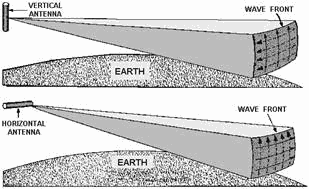 A WAVEFRONT is a small section of an expanding sphere of radiated energy and is
perpendicular to the direction of travel from the antenna. Radio WAVES are
electromagnetic waves that can be reflected, refracted, and diffracted in the atmosphere like light and heat
waves.
REFLECTED Radio WAVES are waves that have been reflected from a surface and are 180 degrees out
of phase with the initial wave.
2-39

The Earth's atmosphere is divided into three separate layers: The TROPOSPHERE,
STRATOSPHERE, and IONOSPHERE. The TROPOSPHERE is the
region of the atmosphere where virtually all weather phenomena take place. In this region, RF energy is greatly
affected.
The STRATOSPHERE has a constant temperature and has little effect on radio waves. The
IONOSPHERE contains four cloud-like layers of electrically charged ions which aid in long
distance communications. Ground WAVES and SKY WAVES are the two basic
types of radio waves that transmit energy from the transmitting antenna to the receiving antenna.
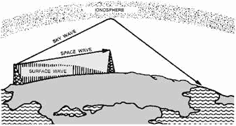 Ground WAVES are composed of two separate component waves: the SURFACE WAVE
and the SPACE WAVE.
2-40
| - |
Matter, Energy,
and Direct Current |
| - |
Alternating Current and Transformers |
| - |
Circuit Protection, Control, and Measurement |
| - |
Electrical Conductors, Wiring Techniques,
and Schematic Reading |
| - |
Generators and Motors |
| - |
Electronic Emission, Tubes, and Power Supplies |
| - |
Solid-State Devices and Power Supplies |
| - |
Amplifiers |
| - |
Wave-Generation and Wave-Shaping Circuits |
| - |
Wave Propagation, Transmission Lines, and
Antennas |
| - |
Microwave Principles |
| - |
Modulation Principles |
| - |
Introduction to Number Systems and Logic Circuits |
| - |
- Introduction to Microelectronics |
| - |
Principles of Synchros, Servos, and Gyros |
| - |
Introduction to Test Equipment |
| - |
Radio-Frequency Communications Principles |
| - |
Radar Principles |
| - |
The Technician's Handbook, Master Glossary |
| - |
Test Methods and Practices |
| - |
Introduction to Digital Computers |
| - |
Magnetic Recording |
| - |
Introduction to Fiber Optics |
| Note: Navy Electricity and Electronics Training
Series (NEETS) content is U.S. Navy property in the public domain. |
|