Module 10 - Introduction to Wave Propagation, Transmission Lines, and Antennas
Pages i,
1-1,
1-11,
1-21,
1-31,
1-41,
2-1,
2-11,
2-21,
2-31,
2-40,
3-1,
3-11,
3-21,
3-31,
3-41,
3-51,
4-1,
4-11,
4-21,
4-31,
4-41,
4-51, Index
Chapter 4
Antennas
Learning Objectives Upon completion of this chapter you will be able to: 1. State the basic principles of antenna
radiation and list the parts of an antenna. 2. Explain current and voltage distribution on an antenna.
3. Describe how electromagnetic energy is radiated from an antenna.
4. Explain polarization, gain, and radiation resistance characteristics of an antenna. 5. Describe the
theory of operation of half- wave and quarter-wave antennas. 6. List the various array antennas.
7. Describe the directional array antennas presented and explain the basic operation of each. 8.
Identify various special antennas presented, such as long-wire, V, rhombic, turnstile, ground-plane, and
corner-reflector; describe the operation of each. 9. List safety precautions when working aloft and
around antennas.
Introduction If you had been around in the early days of electronics, you would have considered an Antenna (AERIAL)
to be little more than a piece of wire strung between two trees or upright poles. In those days, technicians
assumed that longer antennas automatically provided better reception than shorter antennas. They also believed
that a mysterious MEDIUM filled all space, and that an antenna used this medium to send and receive its energy.
These two assumptions have since been discarded. Modern antennas have evolved to the point that highly
directional, specially designed antennas are used to relay worldwide communications in space through the use of
satellites and Earth station antennas (fig. 4-1). Present transmission theories are based on the assumption that
space itself is the only medium necessary to propagate (transmit) radio energy.
4-1
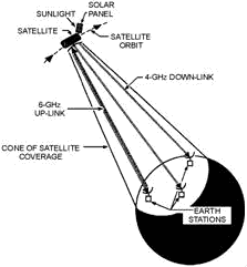
Figure 4-1. - Satellite/earth station communications system. A tremendous amount of knowledge and information has been gained about the design of antennas and
radio-wave propagation. Still, many old-time technicians will tell you that when it comes to designing the length
of an antenna, the best procedure is to perform all calculations and try out the antenna. If it doesn't work
right, use a cut-and-try method until it does. Fortunately, enough information has been collected over the last
few decades that it is now possible to predict the behavior of antennas. This chapter will discuss and explain the
basic design and operation of antennas.
Principles of Antenna Radiation After an RF signal has been generated in a transmitter, some means must be used to radiate this signal
through space to a receiver. The device that does this job is the antenna. The transmitter signal energy is sent
into space by a TRANSMITTING Antenna; the RF signal is then picked up from space by a RECEIVING Antenna.
The RF energy is transmitted into space in the form of an electromagnetic field. As the traveling electromagnetic
field arrives at the receiving antenna, a voltage is induced into the antenna (a conductor). The RF voltages
induced into the receiving antenna are then passed into the receiver and converted back into the transmitted RF
information.
The design of the antenna system is very important in a transmitting station. The antenna must be able to radiate
efficiently so the power supplied by the transmitter is not wasted. An efficient transmitting antenna must have
exact dimensions. The dimensions are determined by the transmitting frequencies. The dimensions of the receiving
antenna are not critical for relatively low radio frequencies. However, as the frequency of the signal being
received increases, the design and installation of the receiving antenna become more critical. An example of this
is a television receiving antenna. If you raise it a few more inches from the ground or give a slight turn in
direction, you can change a snowy blur into a clear picture.
4-2
The conventional antenna is a conductor, or system of conductors, that radiates or intercepts
electromagnetic wave energy. An ideal antenna has a definite length and a uniform diameter, and is completely
isolated in space. However, this ideal antenna is not realistic. Many factors make the design of an antenna for a
communications system a more complex problem than you would expect. These factors include the height of the
radiator above the earth, the conductivity of the earth below it, and the shape and dimensions of the antenna. All
of these factors affect the radiated-field pattern of the antenna in space. Another problem in antenna design is
that the radiation pattern of the antenna must be directed between certain angles in a horizontal or vertical
plane, or both. Most practical transmitting antennas are divided into two basic classifications, Hertz
(half-wave) Antennas and MARCONI (quarter-wave) Antennas. Hertz antennas are generally installed some distance
above the ground and are positioned to radiate either vertically or horizontally. Marconi antennas operate with
one end grounded and are mounted perpendicular to the Earth or to a surface acting as a ground. Hertz antennas are
generally used for frequencies above 2 megahertz. Marconi antennas are used for frequencies below 2 megahertz and
may be used at higher frequencies in certain applications.
a complete antenna system consists of three parts: (1) The Coupling DEVICE, (2) the FEEDER, and (3) the Antenna,
as shown in figure 4-2. The coupling device (coupling coil) connects the transmitter to the feeder. The feeder is
a transmission line that carries energy to the antenna. The antenna radiates this energy into space.
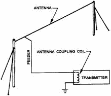
Figure 4-2. - Typical antenna system. The factors that determine the type, size, and shape of the antenna are (1) the frequency of operation
of the transmitter, (2) the amount of power to be radiated, and (3) the general direction of the receiving set.
Typical antennas are shown in figure 4-3.
4-3
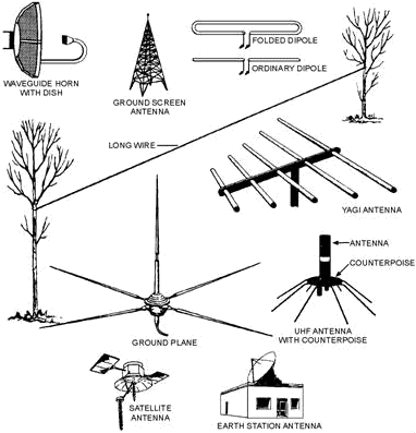
Figure 4-3. - Typical antennas. CURRENT and Voltage DIsTRIBUTION ON an Antenna A current flowing in a wire
whose length is properly related to the RF produces an electro magnetic field. This field is radiated from the
wire and is set free in space. We will discuss how these waves are set free later in this chapter. Remember, the
principles of radiation of electromagnetic energy are based on two laws: 1. a MOVING ELECTRIC FIELD
CREATES a Magnetic (H) FIELD. 2. a MOVING Magnetic FIELD CREATES an ELECTRIC (E) FIELD. In
space, these two fields will be in phase and perpendicular to each other at any given time. Although a conductor
is usually considered present when a moving electric or magnetic field is mentioned, the laws that govern these
fields say nothing about a conductor. Therefore, these laws hold true whether a conductor is present or not.
4-4
Figure 4-4 shows the current and voltage distribution on a half-wave (Hertz) antenna. In view A, a piece of
wire is cut in half and attached to the terminals of a high-frequency ac generator. The frequency of the generator
is set so that each half of the wire is 1/4 wavelength of the output. The result is a common type of antenna known
as a DIPOLE.
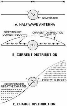
Figure 4-4. - Current and voltage distribution on an antenna. At a given time the right side of the generator is positive and the left side negative. Remember that
like charges repel. Because of this, electrons will flow away from the negative terminal as far as possible, but
will be attracted to the positive terminal. View B shows the direction and distribution of electron flow. The
distribution curve shows that most current flows in the center and none flows at the ends. The current
distribution over the antenna will always be the same no matter how much or how little current is flowing.
However, current at any given point on the antenna will vary directly with the amount of voltage developed by the
generator. One-quarter cycle after electrons have begun to flow, the generator will develop its maximum
voltage and the current will decrease to 0. At that time the condition shown in view C will exist. No current will
be flowing, but a maximum number of electrons will be at the left end of the line and a minimum number at the
right end. The charge distribution view C along the wire will vary as the voltage of the generator varies.
Therefore, you may draw the following conclusions:
4-5
1. a current flows in the antenna with an amplitude that varies with the generator voltage.
2. a sinusoidal distribution of charge exists on the antenna. Every 1/2 cycle, the charges reverse polarity.
3. The sinusoidal variation in charge magnitude lags the sinusoidal variation in current by 1/4 cycle.
Q1. What are the two basic classifications of antennas? Q2. What are the three parts of a complete
antenna system? Q3. What three factors determine the type, size, and shape of an antenna?
Radiation of ELECTROMagnetic ENERGY The electromagnetic radiation from an antenna is made up of
two components, the E field and the H field. We discussed these fields in chapters 1 and 2. The two fields occur
90 degrees out of phase with each other. These fields add and produce a single electromagnetic field. The total
energy in the radiated wave remains constant in space except for some absorption of energy by the Earth. However,
as the wave advances, the energy spreads out over a greater area and, at any given point, decreases as the
distance increases. Various factors in the antenna circuit affect the radiation of these waves. In figure
4-5, for example, if an alternating current is applied at the a end of the length of wire from a to B, the wave
will travel along the wire until it reaches the B end. Since the B end is free, an open circuit exists and the
wave cannot travel farther. This is a point of high impedance. The wave bounces back (reflects) from this point of
high impedance and travels toward the starting point, where it is again reflected. The energy of the wave would be
gradually dissipated by the resistance of the wire of this back-and-forth motion (oscillation); however, each time
it reaches the starting point, the wave is reinforced by an amount sufficient to replace the energy lost. This
results in continuous oscillations of energy along the wire and a high voltage at the a end of the wire. These
oscillations are applied to the antenna at a rate equal to the frequency of the RF voltage.
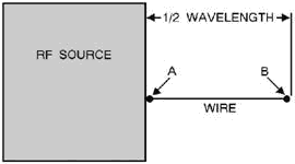
Figure 4-5. - Antenna and RF source. These impulses must be properly timed to sustain oscillations in the antenna. The rate at which the
waves travel along the wire is constant at approximately 300,000,000 meters per second. The length of
4-6
the antenna must be such that a wave will travel from one end to the other and back again during the
period of 1 cycle of the RF voltage. Remember, the distance a wave travels during the period of 1 cycle is known
as the wavelength and is found by dividing the rate of travel by the frequency. Look at the current and
voltage (charge) distribution on the antenna in figure 4-6. a maximum movement of electrons is in the center of
the antenna at all times; therefore, the center of the antenna is at a low impedance. This condition is called a
Standing WAVE of current. The points of high current and high voltage are known as current and voltage LoopS. The
points of minimum current and minimum voltage are known as current and voltage NODES. View a shows a current loop
and current nodes. View B shows voltage loops and a voltage node. View C shows the resultant voltage and current
loops and nodes. The presence of standing waves describes the condition of resonance in an antenna. At resonance
the waves travel back and forth in the antenna reinforcing each other and the electromagnetic waves are
transmitted into space at maximum radiation. When the antenna is not at resonance, the waves tend to cancel each
other and lose energy in the form of heat.
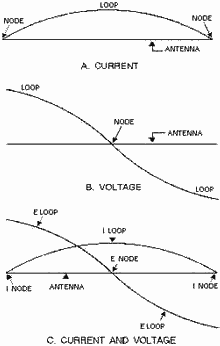
Figure 4-6. - Standing waves of voltage and current on an antenna. Q4. If a wave travels exactly the length of an antenna from one end to the other and back during the
period of 1 cycle, what is the length of the antenna?
4-7
Q5. What is the term used to identify the points of high current and high voltage on an antenna?
Q6. What is the term used to identify the points of minimum current and minimum voltage on an antenna?
Antenna Characteristics You can define an antenna as a conductor or group of conductors used either for radiating
electromagnetic energy into space or for collecting it from space. Electrical energy from the transmitter is
converted into electromagnetic energy by the antenna and radiated into space. On the receiving end,
electromagnetic energy is converted into electrical energy by the antenna and is fed into the receiver.
Fortunately, separate antennas seldom are required for both transmitting and receiving RF energy. Any antenna can
transfer energy from space to its input receiver with the same efficiency that it transfers energy from the
transmitter into space. Of course, this is assuming that the same frequency is used in both cases. This property
of interchangeability of the same antenna for transmitting and receiving is known as antenna RECIPROCITY. Antenna
reciprocity is possible because antenna characteristics are essentially the same for sending and receiving
electromagnetic energy. RECIPROCITY of Antennas
In general, the various properties of an antenna apply equally, regardless of whether you use the antenna for
transmitting or receiving. The more efficient a certain antenna is for transmitting, the more efficient it will be
for receiving on the same frequency. Likewise, the directive properties of a given antenna also will be the same
whether it is used for transmitting or receiving. Assume, for example, that a certain antenna used with a
transmitter radiates a maximum amount of energy at right angles to the axis of the antenna, as shown in figure
4-7, view A. Note the minimum amount of radiation along the axis of the antenna. Now, if this same antenna were used as a receiving antenna, as shown in view B, it would receive best in the same directions in which it produced
maximum radiation; that is, at right angles to the axis of the antenna.
4-8

Figure 4-7. - Reciprocity of antennas. Antenna Gain Another characteristic of a given antenna that remains the same
whether the antenna is used for transmitting or receiving is Gain. Some antennas are highly directional that is,
more energy is propagated in certain directions than in others. The ratio between the amount of energy propagated
in these directions compared to the energy that would be propagated if the antenna were not directional is known
as its gain. When a transmitting antenna with a certain gain is used as a receiving antenna, it will also have the
same gain for receiving. POLARIZATION Let's review polarization briefly. In
chapter 2 you learned that the radiation field is composed of electric and magnetic lines of force. These lines of
force are always at right angles to each other. Their intensities rise and fall together, reaching their maximums
90 degrees apart. The electric field determines the direction of polarization of the wave. In a vertically
polarized wave, the electric lines of force lie in a vertical direction. In a horizontally polarized wave, the
electric lines of force lie in a horizontal direction. Circular polarization has the electric lines of force
rotating through 360 degrees with every cycle of RF energy. The electric field was chosen as the reference
field because the intensity of the wave is usually measured in terms of the electric field intensity (volts,
millivolts, or microvolts per meter). When a single-wire antenna is used to extract energy from a passing radio
wave, maximum pickup will result when the antenna is oriented in the same direction as the electric field. Thus a
vertical antenna is used for the efficient reception of vertically polarized waves, and a horizontal antenna is used for the reception of horizontally polarized waves. In some cases the orientation of the electric field does
not remain constant.
4-9
Instead, the field rotates as the wave travels through space. Under these conditions both horizontal
and vertical components of the field exist and the wave is said to have an elliptical polarization. Q7.
The various properties of a transmitting antenna can apply equally to the same antenna when it is used as a
receiving antenna. What term is used for this property? Q8. The direction of what field is used to
designate the polarization of a wave? Q9. If a wave's electric lines of force rotate through 360 degrees
with every cycle of RF energy, what is the polarization of this wave? Polarization Requirements
for Various Frequencies Ground-wave transmission is widely used at medium and low frequencies.
Horizontal polarization cannot be used at these frequencies because the electric lines of force are parallel to
and touch the earth. Since the earth acts as a fairly good conductor at low frequencies, it would short out the
horizontal electric lines of force and prevent the radio wave from traveling very far. Vertical electric lines of
force, on the other hand, are bothered very little by the earth. Therefore vertical polarization is used for
ground-wave transmission, allowing the radio wave to travel a considerable distance along the ground surface with
minimum attenuation.
Sky-wave transmission is used at high frequencies. Either horizontal or vertical polarization can be used with
sky-wave transmission because the sky wave arrives at the receiving antenna elliptically polarized. This is the
result of the wave traveling obliquely through the Earth's magnetic field and striking the ionosphere. The radio
wave is given a twisting motion as it strikes the ionosphere. Its orientation continues to change because of the
unstable nature of the ionosphere. The relative amplitudes and phase differences between the horizontal and
vertical components of the received wave also change. Therefore, the transmitting and receiving antennas can be
mounted either horizontally or vertically. Although either horizontally or vertically polarized antennas
can be used for high frequencies, horizontally polarized antennas have certain advantages and are therefore
preferred. One advantage is that vertically polarized interference signals, such as those produced by automobile
ignition systems and electrical appliances, are minimized by horizontal polarization. Also, less absorption of
radiated energy by buildings or wiring occurs when these antennas are used. Another advantage is that support
structures for these antennas are of more convenient size than those for vertically polarized antennas.
For frequencies in the vhf or uhf range, either horizontal or vertical polarization is satisfactory. These radio
waves travel directly from the transmitting antenna to the receiving antenna without entering the ionosphere. The
original polarization produced at the transmitting antenna is maintained throughout the entire travel of the wave
to the receiver. Therefore, if a horizontally polarized antenna is used for transmitting, a horizontally polarized
antenna must be used for receiving. The requirements would be the same for a vertical transmitting and receiving
antenna system. For satellite communications, parallel frequencies can be used without interference by
using polarized radiation. The system setup is shown in figure 4-8. One pair of satellite antennas is vertically
polarized and another pair is horizontally polarized. Either vertically or horizontally polarized transmissions
are received by the respective antenna and retransmitted in the same polarization. For example, transmissions may
be made in the 3.7 to 3.74 GHz range on the vertical polarization path and in the 3.72 to 3.76 GHz range on the
horizontal polarization path without adjacent frequency (co-channel) interference. 4-10
| - |
Matter, Energy,
and Direct Current |
| - |
Alternating Current and Transformers |
| - |
Circuit Protection, Control, and Measurement |
| - |
Electrical Conductors, Wiring Techniques,
and Schematic Reading |
| - |
Generators and Motors |
| - |
Electronic Emission, Tubes, and Power Supplies |
| - |
Solid-State Devices and Power Supplies |
| - |
Amplifiers |
| - |
Wave-Generation and Wave-Shaping Circuits |
| - |
Wave Propagation, Transmission Lines, and
Antennas |
| - |
Microwave Principles |
| - |
Modulation Principles |
| - |
Introduction to Number Systems and Logic Circuits |
| - |
- Introduction to Microelectronics |
| - |
Principles of Synchros, Servos, and Gyros |
| - |
Introduction to Test Equipment |
| - |
Radio-Frequency Communications Principles |
| - |
Radar Principles |
| - |
The Technician's Handbook, Master Glossary |
| - |
Test Methods and Practices |
| - |
Introduction to Digital Computers |
| - |
Magnetic Recording |
| - |
Introduction to Fiber Optics |
| Note: Navy Electricity and Electronics Training
Series (NEETS) content is U.S. Navy property in the public domain. |
|


