Behavior of Radio Waves
There are a few simple rules of thumb that can prove extremely useful when making
first plans for a wireless network:
- the longer the wavelength, the further it goes
- the longer the wavelength, the better it travels through and around things
- the shorter the wavelength, the more data it can transport
All of these rules, simplified as they may be, are rather easy to understand
by example.
Longer Waves Travel Further
Waves with longer wavelengths tend to travel further than waves with shorter
wavelengths. As an example, AM radio stations have a much greater range than FM
stations, which use a frequency 100 times higher. Lower frequency transmitters tend
to reach much greater distances than high frequency transmitters at the same power.
Longer Waves Pass Around Obstacles
A wave on water which is 5 metres long will not be affected by a 5 mm piece of
wood floating on the water. If instead the piece of wood were 50 metres big (e.g.
a ship), it would modify the behavior of the wave.
The distance a wave can travel depends on the relationship between the wavelength
of the wave and the size of obstacles in its path of propagation. It is harder to
visualize waves moving "through" solid objects, but this is the case with electromagnetic
waves. Longer wavelength (and therefore lower frequency) waves tend to penetrate
objects better than shorter wavelength (and therefore higher frequency) waves.
For example, FM radio (88-108 MHz) can travel through buildings and other obstacles
easily, while shorter waves (such as GSM phones operating at 900 MHz or 1800 MHz)
have a harder time penetrating buildings.
This effect is partly due to the difference in power levels used for FM radio
and GSM, but is also partly due to the shorter wavelength of GSM signals. At much
higher frequencies, visible light does not go through a wall or even 1 mm of wood
- as we all know, from practical experience. But metal will stop any kind of electromagnetic
wave.
Shorter Waves Can Carry More Data
The faster the wave swings or beats, the more information it can carry - every
beat or cycle could for example be used to transport a digital bit, a '0' or a '1',
a 'yes' or a 'no'.
So the data rate scales with bandwidth, and can be further enhanced by advanced
modulation and media access techniques such as OFDM, and MIMO (Multiple Input, Multiple
Output).
The Huygens Principle
There is another principle that can be applied to all kinds of waves, and which
is extremely useful for understanding radio wave propagation. This principle is
known as the Huygens Principle, named after Christiaan Huygens, Dutch mathematician,
physicist and astronomer, 1629 - 1695.
Imagine you are taking a little stick and dipping it vertically into a still
lake's surface, causing the water to swing and dance. Waves will leave the center
of the stick - the place where you dip in - in circles. Now, wherever water particles
are swinging and dancing, they will cause their neighbor particles to do the same:
from every point of disturbance, a new circular wave will start. This is, in simple
form, the Huygens principle. In the words of wikipedia.org:
"The Huygens' principle is a method of analysis applied to problems of wave propagation
in the far field limit. It recognizes that each point of an advancing wave front
is in fact the center of a fresh disturbance and the source of a new train of waves;
and that the advancing wave as a whole may be regarded as the sum of all the secondary
waves arising from points in the medium already traversed."
This view of wave propagation helps better understand a variety of wave phenomena,
such as diffraction."
This principle holds true for radio waves as well as waves on water, for sound
as well as light, but for light the wavelength is far too short for human beings
to actually see the effects directly.
This principle will help us to understand diffraction as well as Fresnel zones,
and the fact that sometimes we seem to be able to transmit around corners, with
no line of sight.
Let us now look into what happens to electromagnetic waves as they travel.
Absorption
When electromagnetic waves go through 'something' (some material), they generally
get weakened or dampened.
How much they lose in power will depend on their frequency and of course the
material.
Clear window glass is obviously transparent for light, while the glass used in
sunglasses filters out quite a share of the light intensity and most of the ultraviolet
radiation.
Often, an absorption coefficient is used to describe a material's impact on radiation.
For microwaves, the two main absorbent materials are:
Metal
Electrons can move freely in metals, and are readily able to swing and thus absorb
the energy of a passing wave.
Water
Microwaves cause water molecules to jostle around, thus taking away some of the
wave's energy.
For the purpose of practical wireless networking, we may well consider metal
and water perfect absorbers: we will not be able to go through them (although thin
layers of water will let some power pass). They are to microwave what a brick wall
is to light.
When talking about water, we have to remember that it comes in different forms:
rain, fog and mist, low clouds and so forth, all will be in the way of radio links.
They have a strong influence, and in many circumstances a change in weather can
bring a radio link down.
When talking about metal, keep in mind that it may be found in unexpected places:
it may be hidden in walls (for example, as metal grids in concrete) or be a thin
coat on modern types of glass (tinted glass, colored glass).
However thin the layer of metal, it might be enough to significantly absorb a
radio wave.
There are other materials that have a more complex effect on radio absorption.
For trees and wood, the amount of absorption depends on how much water they contain.
Old dead dry wood is more or less transparent, wet fresh wood will absorb a lot.
Plastics and similar materials generally do not absorb a lot of radio energy, but
this varies depending on the frequency and type of material. Lastly, let us talk
about ourselves: humans (as well as other animals) are largely made out of water.
As far as radio networking is concerned, we may well be described as big bags
of water, with the same strong absorption.
Orienting an office access point in such a way that its signal must pass through
many people is a key mistake when building office networks. The same goes for hotspots,
cafe installations, libraries, and outdoor installations.
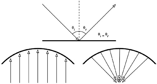
Reflection

Figure RP 6 - Reflection of radio waves. The angle of incidence
is always equal to the angle of reflection. A metal parabolic surface uses this
effect to concentrate radio waves spread out over it in a common direction.
Just like visible light, radio waves are reflected when they come in contact
with materials that are suited for that: for radio waves, the main sources of reflection
are metal and water surfaces.
The rules for reflection are quite simple: the angle at which a wave hits a surface
is the same angle at which it gets deflected.
Note that in the eyes of a radio wave, a dense grid of bars acts just the same
as a solid surface, as long as the distance between bars is small compared to the
wavelength.
At 2.4 GHz, a one cm metal grid will act much the same as a metal plate.
Although the rules of reflection are quite simple, things can become very complicated
when you imagine an office interior with many many small metal objects of various
complicated shapes.
The same goes for urban situations: look around you in city environment and try
to spot all of the metal objects.
This explains why multipath effects (i.e. signal reaching their target along
different paths, and therefore at different times) play such an important role in
wireless networking.
Water surfaces, with waves and ripples changing all the time, effectively make
for a very complicated reflection object which is more or less impossible to calculate
and predict precisely.
We should also add that polarization has an impact: waves of different polarization
in general will be reflected differently.
We use reflection to our advantage in antenna building: e.g. we put huge parabolas
behind our radio transmitter/receiver to collect and bundle the radio signal into
a single point, the focal point.
Diffraction
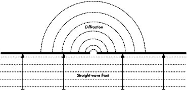
Figure RP 7 - Diffraction through a narrow slit.
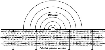
Figure RP 8 - The Huygens Principle.
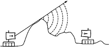
Figure RP 9 - Diffraction over a mountain top.
Diffraction is the apparent bending of waves when hitting an object. It is the
effect of "waves going around corners". Imagine a wave on water traveling in a straight
wave front, just like a wave that we see rolling onto an ocean beach.
Now we put a solid barrier, say a wooden solid fence, in its way to block it.
We cut a narrow slit opening into that wall, like a small door.
From this opening, a circular wave will start, and it will of course reach points
that are not in a direct line behind this opening, but also on either side of it.
If you look at this wavefront - and it might just as well be an electromagnetic
wave - as a beam (a straight line), it would be hard to explain how it can reach
points that should be hidden by a barrier.
When modeled as a wavefront, the phenomenon makes sense.
The Huygens Principle provides one model for understanding this behavior. Imagine
that at any given instant, every point on a wavefront can be considered the starting
point for a spherical "wavelet".
This idea was later extended by Fresnel, and whether it adequately describes
the phenomenon is still a matter of debate. But for our purposes, the Huygens model
describes the effect quite well.
Through means of the effect of diffraction, waves will "bend" around corners
or spread through an opening in a barrier.
The wavelengths of visible light are far too small for humans to observe this
effect directly.
Microwaves, with a wavelength of several centimeters, will show the effects of
diffraction when waves hit walls, mountain peaks, and other obstacles. It seems
as if the obstruction causes the wave to change its direction and go around corners.
Note that diffraction comes at the cost of power: the energy of the diffracted
wave is significantly less than that of the wavefront that caused it. But in some
very specific applications, you can take advantage of the diffraction effect to
circumvent obstacles.
Interference
Interference is one of the most misunderstood terms and phenomena in wireless
networking.
Interference often gets the blame when we are too lazy to find the real problem,
or when a regulator wants to shut down someone else's network for business reasons.
So, why all the misunderstandings?
It is mostly because different people mean different things though they are using
the same word.
A physicist and a telecommunications engineer will use the word "Interference"
in very different ways. The physicists' view will be concerned with the "behavior
of waves". The telecommunications engineer will talk about "... any noise that gets
in the way."
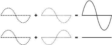
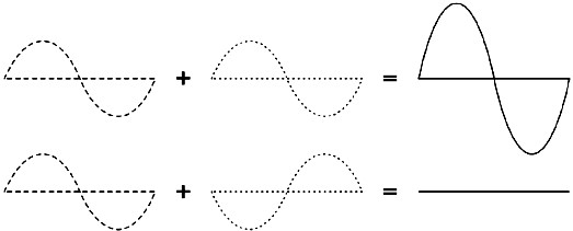
Figure RP 10 - Constructive and destructive interference.
Both views are relevant in wireless, and it is important to be able to know them
both and know the difference. Let us start with the physicists' view: When working
with waves, one plus one does not necessarily equal two. It can also result in zero.
This is easy to understand when you draw two sine waves and add up the amplitudes.
When the phase difference is zero, peak hits peak, and you will have maximum results
(1 + 1 = 2).
This is called constructive interference.
When the phase difference is 180 degrees, or λ/2, peak hits valley, and you will
have complete annihilation ((1 + (-)1 = 0) - destructive interference.
You can actually try this with waves on water and two little sticks to create
circular waves - you will see that where two waves cross, there will be areas of
higher wave peaks and others that remain almost flat and calm. In order for whole
trains of waves to add up or cancel each other out perfectly, they have to have
the exact same wavelength and a fixed phase relation.
You can see obvious examples of interference in action when you look at the way
that antennas are arranged in what are called beamforming arrays, in order to give
maximum constructive interference in the directions where you want the signal, and
destructive interference (no signal) where you want no signal.
Technically, this is achieved by a combination of physical dimensioning and control
of phase shifts.
Simplified, imagine that you have three antennas - and you don't want antenna
3 to pick up signal from antenna 1 and 2. You would then place antenna 3 at a position
where the signals from antennas 1 and 2 cancel each other out.
Now let us have a look at the way the word interference is typically used: in
a wider sense, for any disturbance through other RF sources, any noise that might
get in our way, e.g. from neighboring channels or competing providers. So, when
wireless networkers talk about interference they typically talk about all these
kinds of disturbance by other networks, and any other sources of microwave, whether
it has exactly the same frequency and a fixed phase relation or not. Interference
of this kind is one of the main sources of difficulty in building wireless links,
especially in urban environments or closed spaces (such as a conference space) where
many networks may compete for use of the spectrum.
But, interference of this kind is also often overrated: for example, imagine
you had to build a point to point link that has to cross a crowded inner city area,
before reaching its target on the other side of the city. Such a highly directional
beam will cross the "electric smog" of the urban center without any problem. You
may imagine this like a green and a red light beam crossing each other in a 90 degrees
angle: while both beams will overlap in a certain area, the one will not have any
impact on the other at all.
Generally, managing spectrum and coexistence has become a main issue especially
in dense indoor environments and urban areas.
Line of Sight
The term line of sight, often abbreviated as LOS, is quite easy to understand
when talking about visible light: if we can see a point B from point A where we
are, we have line of sight. Simply draw a line from A to B, and if nothing is in
the way, we have line of sight.
Things get a bit more complicated when we are dealing with microwaves. Remember
that most propagation characteristics of electromagnetic waves scale with their
wavelength.
This is also the case for the widening of waves as they travel.
Light has a wavelength of about 0.5 micrometers, microwaves as used in wireless
networking have a wavelength of a few centimeters.
Consequently, their beams are a lot wider - they need more space, so to speak.
Note that visible light beams widen just the same, and if you let them travel
long enough, you can see the results despite their short wavelength. When pointing
a well focused laser at the moon, its beam will widen to well over 100 meters in
radius by the time it reaches the surface. You can see this effect for yourself
using an inexpensive laser pointer and a pair of binoculars on a clear night. Rather
than pointing at the moon, point at a distant mountain or unoccupied structure (such
as a water tower). The radius of your beam will increase as the distance increases.
This is due to the diffraction.
The line of sight that we need in order to have an optimal wireless connection
from A to B is more than just a thin line - its shape is more like that of a cigar,
an ellipsoid. Its width can be described by the concept of Fresnel zones - see next
section for an explanation. You will also find the abbreviation NLOS, for "non line
of sight", which is mostly used to describe and advertise technologies that allow
for dealing with waves that reach the receiver through multiple trajectories (multipath)
or diffraction. It does not indicate that the single electromagnetic beam goes "around
corners" (other than through diffraction) or "through obstacles" any better than
that of other technologies. For example, you might call White Space technology NLOS,
as its lower frequencies (longer wavelengths) allow it to permeate objects and utilize
diffraction much better than comparable 2.4 GHz or 5 GHz transmissions.