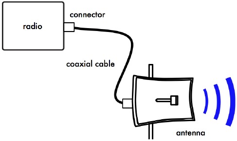
The transmitter that generates the RF power to drive the antenna is usually located
at some distance from the antenna terminals. The connecting link between the two
is the RF transmission line. Its purpose is to carry RF power from one place to
another, and to do this as efficiently as possible. From the receiver side, the
antenna is responsible for picking up any radio signals in the air and passing them
to the receiver with the minimum amount of distortion and maximum efficiency, so
that the radio has its best chance to decode the signal. For these reasons, the
RF cable has a very important role in radio systems: it must maintain the integrity
of the signals in both directions.
The simplest transmission line one can envisage is the bifilar or twin lead,
consisting of two conductors separated by a dielectric or insulator. The dielectric
can be air or a plastic like the one used for flat transmission lines used in TV
antennas. A bifilar transmission line open at one end will not radiate because the
current in each wire has the same value but opposite direction, so that the fields
created on a given point at some distance from the line cancel.

Figure ATL 1 - Radio, transmission line and antenna.
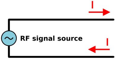
Figure ATL 2 - Bifilar transmission line.
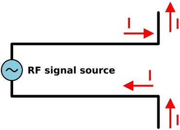
Figure ATL 3 - Antenna from transmission line.
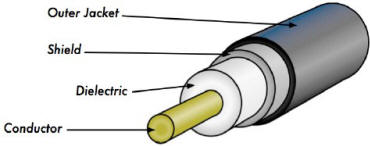
Figure ATL 4 - Coaxial cable with jacket, shield, dielectric,
and core conductor.
If we bend the open ends of the transmission line in opposite directions, the
currents will now generate electric fields that are in phase and reinforce each
other and will therefore radiate and propagate at a distance. We now have an antenna
at the end of the transmission line.
The length of the bent portion of the transmission line will determine the antenna
feature. If this length corresponds to a quarter of a wavelength we will have a
half wave dipole antenna with a gain of 2.15 dBi.
The functioning of the bifilar transmission line just described is strongly affected
by any metal in its proximity, so a better solution is to confine the electrical
fields by means of an external conductor that shields the internal one. This constitutes
a coaxial cable. Alternatively, a hollow metallic pipe of the proper dimensions
will also effectively carry RF energy in what is known as a waveguide.
Cables
For frequencies higher than HF the coaxial cables (or coax for short, derived
from the words "of common axis") are used almost exclusively. Coax cables have a
core conductor wire surrounded by a non-conductive material called dielectric, or
simply insulation.
The dielectric is then surrounded by an encompassing shielding which is often
made of braided wires. The dielectric prevents an electrical connection between
the core and the shielding. Finally, the coax is protected by an outer casing which
is generally made from a PVC material.
The inner conductor carries the RF signal, and the outer shield prevents the
RF signal from radiating to the atmosphere, and also prevents outside signals from
interfering with the signal carried by the core. Another interesting fact is that
high frequency electrical signal travels only along the outer layer of a conductor,
the inside material does not contribute to the conduction, hence the larger the
central conductor, the better the signal will flow. This is called the "skin
effect."
Even though the coaxial construction is good at transporting the signal, there
is always resistance to the electrical flow: as the signal travels along, it will
fade away.
This fading is known as attenuation, and for transmission lines it is measured
in decibels per meter (dB/m).
The rate of attenuation is a function of the signal frequency and the physical
construction of the cable itself. As the signal frequency increases, so does its
attenuation.
Obviously, we need to minimize the cable attenuation as much as possible by keeping
the cable very short and using high quality cables.
Here are some points to consider when choosing a cable for use with microwave
devices:
- "The shorter the better!" The first rule when you install a piece of cable is
to try to keep it as short as possible. The power loss is not linear, so doubling
the cable length means that you are going to lose much more than twice the power.
In the same way, reducing the cable length by half gives you more than twice the
power at the antenna. The best solution is to place the transmitter as close as
possible to the antenna, even when this means placing it on a tower.
- "The cheaper the worse!" The second golden rule is that any money you invest
in buying a good quality cable is a bargain. Cheap cables can be used at low frequencies,
such as VHF. Microwaves require the highest quality cables available.
- Avoid RG-58. It is intended for thin Ethernet networking, CB or VHF radio, not
for microwave.
- Avoid RG-213 or RG-8. They are intended for CB and HF radio. In this case even
if the diameter is large the attenuation is significant due to the cheap insulator
used.
- Whenever possible, use the best rated LMR cable or equivalent you can find.
LMR is a brand of coax cable available in various diameters that works well at microwave
frequencies. The most commonly used are LMR-400 and LMR-600. Heliax cables are also
very good, but expensive and difficult to use.
- Whenever possible, use cables that are pre-crimped and tested in a proper lab.
Installing connectors to cable is a tricky business, and is difficult to do properly
even with the specific tools. Never step over a cable, bend it too much, or try
to unplug a connector by pulling the cable directly. All of these behaviors may
change the mechanical characteristic of the cable and therefore its impedance, short
the inner conductor to the shield, or even break the line.
- Those problems are difficult to track and recognize and can lead to unpredictable
behavior on the radio link.
- For very short distances, a thin cable of good quality maybe adequate since
it will not introduce too much attenuation.
Waveguides
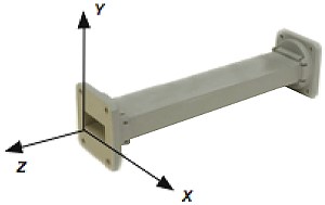
Figure ATL 5 - The X, Y, and Z axis of a rectangular waveguide.
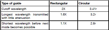
Waveguide specifications.
Above 2 GHz, the wavelength is short enough to allow practical, efficient energy
transfer by different means. A waveguide is a conducting tube through which energy
is transmitted in the form of electromagnetic waves. The tube acts as a boundary
that confines the waves in the enclosed space. The Faraday cage phenomenon prevents
electromagnetic effects from being evident outside the guide. The electromagnetic
fields are propagated through the waveguide by means of reflections against its
inner walls, which are considered perfect conductors. The intensity of the fields
is greatest at the center along the X dimension, and must diminish to zero at the
end walls because the existence of any field parallel to the walls at the surface
would cause an infinite current to flow in a perfect conductor.
The X, Y and Z axis of a rectangular waveguide can be seen in the following figure:
There are an infinite number of ways in which the electric and magnetic fields
can arrange themselves in a waveguide for frequencies above the low cutoff. Each
of these field configurations is called a mode. The modes may be separated into
two general groups. One group, designated TM (Transverse Magnetic), has the magnetic
field entirely transverse to the direction of propagation, but has a component of
the electric field in the direction of propagation. The other type, designated TE
(Transverse Electric) has the electric field entirely transverse, but has a component
of magnetic field in the direction of propagation.
The mode of propagation is identified by the group letters followed by two subscript
numerals. For example, TE 10, TM 11, etc.
The number of possible modes increases with the frequency for a given size of
guide, and there is only one possible mode, called the dominant mode, for the lowest
frequency that can be transmitted. In a rectangular guide, the critical dimension
is X. This dimension must be more than 0.5 λ at the lowest frequency to be transmitted.
In practice, the Y dimension is usually about 0.5 X to avoid the possibility of
operation in other than the dominant mode. Cross-sectional shapes other than the
rectangle can be used, the most important being the circular pipe. Much the same
considerations apply as in the rectangular case. Wavelength dimensions for rectangular
and circular guides are given in the following table, where X is the width of a
rectangular guide and r is the radius of a circular guide. All figures apply to
the dominant mode.
Energy may be introduced into or extracted from a waveguide by means of either
the electric or magnetic field. The energy transfer typically happens through a
coaxial line. Two possible methods for coupling to a coaxial line are using the
inner conductor of the coaxial line, or through a loop. A probe which is simply
a short extension of the inner conductor of the coaxial line can be oriented so
that it is parallel to the electric lines of force. A loop can be arranged so that
it encloses some of the magnetic lines of force. The point at which maximum coupling
is obtained depends upon the mode of propagation in the guide or cavity. Coupling
is maximum when the coupling device is in the most intense field.
If a waveguide is left open at one end, it will radiate energy (that is, it can
be used as an antenna rather than a transmission line).
This radiation can be enhanced by flaring the waveguide to form a pyramidal horn
antenna. T here are examples of practical waveguide antennas for WiFi shown in Appendix
A called Antenna Construction. 60 PHYSICS
Connectors and Adapters
Connectors allow a cable to be connected to another cable or to a component in
the RF chain. There are a wide variety of fittings and connectors designed to go
with various sizes and types of coaxial lines. We will describe some of the most
popular ones.
BNC connectors were developed in the late 40s. BNC stands for Bayonet Neill Concelman,
named after the men who invented it: Paul Neill and Carl Concelman. The BNC product
line is a miniature quick connect/disconnect connector. It features two bayonet
lugs on the female connector, and mating is achieved with only a quarter turn of
the coupling nut. BNCs are ideally suited for cable termination for miniature to
subminiature coaxial cable (RG-58 to RG-179, RG-316, etc.). They are most commonly
found on test equipment and 10base2 coaxial Ethernet cables.
TNC connectors were also invented by Neill and Concelman, and are a threaded
variation of the BNC. Due to the better interconnect provided by the threaded connector,
TNC connectors work well through about 12 GHz. TNC stands for Threaded Neill Concelman.
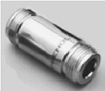
Figure ATL 6 - An N female barrel adapter.
Type N (again for Neill, although sometimes attributed to "Navy") connectors
were originally developed during the Second World War. They are usable up to 18
GHz, and very commonly used for microwave applications. They are available for almost
all types of cable. Both the plug / cable and plug / socket joints are supposedly
waterproof, providing an effective cable clamp. Nevertheless for outdoor use they
should be wrapped in self agglomerating tape to prevent water from seeping in.
SMA is an acronym for Sub Miniature version A, and was developed in the 60s.
SMA connectors are precision, subminiature units that provide excellent electrical
performance up to 18 GHz. These threaded high-performance connectors are compact
in size and mechanically have outstanding durability. The SMB name derives from
Sub Miniature B, and it is the second subminiature design.
The SMB is a smaller version of the SMA with snap-on coupling. It provides broadband
capability through 4 GHz with a snap-on connector design. 5.
MCX connectors were introduced in the 80s.
While the MCX uses identical inner contact and insulator dimensions as the SMB,
the outer diameter of the plug is 30% smaller than the SMB. This series provides
designers with options where weight and physical space are limited. MCX provides
broadband capability though 6 GHz with a snap-on connector design.
In addition to these standard connectors, most WiFi devices use a variety of
proprietary connectors. Often, these are simply standard microwave connectors with
the center conductor parts reversed, or the thread cut in the opposite direction.
These parts are often integrated into a microwave system using a short, flexible
jumper called a pigtail that converts the non-standard connector into something
more robust and commonly available. Some of these connectors include:
RP-TNC. This is a TNC connector with the genders reversed.
U.FL (also known as MHF). This is possibly the smallest microwave connector currently
in wide use. The U.FL/MHF is typically used to connect a mini-PCI radio card to
an antenna or larger connector (such as an N or TNC) using a thin cable in what
is known as a pigtail.
The MMCX series, which is also called a MicroMate, is one of the smallest RF
connector line and was developed in the 90s. MMCX is a micro-miniature connector
series with a lock-snap mechanism allowing for 360 degrees rotation enabling flexibility.
MC-Card connectors are even smaller and more fragile than MMCX. They have a split
outer connector that breaks easily after just a few interconnects.
Adapters are short, two-sided devices which are used to join two cables or components
which cannot be connected directly. For example, an adapter can be used to connect
an SMA connector to a BNC.
Adapters may also be used to fit together connectors of the same type, but of
different gender. Figure ATL 6: An N female barrel adapter.
For example a very useful adapter is the one which enables to join two Type N
connectors, having socket (female) connectors on both sides.
Choosing the Proper Connector
"The gender question." Most connectors have a well defined gender. Male connectors
have an external housing or sleeve (frequently with an inner thread) that is meant
to surround the body of the female connector. They normally have a pin that inserts
in the corresponding socket of the female connector, which has a housing threaded
on the outer surface or two bayonet studs protruding from a cylinder. Beware of
reverse polarity connectors, in which the male has an inner socket and the female
an inner pin. Usually cables have male connectors on both ends, while RF devices
(i.e. transmitters and antennas) have female connectors. Lightning arrestors, directional
couplers and line-through measuring devices may have both male and female connectors.
Be sure that every male connector in your system mates with a female connector.
"Less is best!" Try to minimize the number of connectors and adapters in the
RF chain. Each connector introduces some additional loss (up to a dB for each connection,
depending on the connector!)
"Buy, don't build!" As mentioned earlier, buy cables that are already terminated
with the connectors you need whenever possible. Soldering connectors is not an easy
task, and to do this job properly is almost impossible for small connectors as U.FL
and MMCX. Even terminating "Foam" cables is not an easy task. Don't use BNC for
2.4 GHz or higher. Use N type connectors (or SMA, SMB, TNC, etc.)
Microwave connectors are precision-made parts, and can be easily damaged by mistreatment.
As a general rule, you should rotate the outer sleeve to tighten the connector,
leaving the rest of the connector (and cable) stationary. If other parts of the
connector are twisted while tightening or loosening, damage can easily occur.
Never step over connectors, or drop connectors on the floor when disconnecting
cables (this happens more often than you may imagine, especially when working on
a mast over a roof).
Never use tools like pliers to tighten connectors. Always use your hands. When
working outside, remember that metals expand at high temperatures and contract at
low temperatures: connector too tight in the summer can bind or even break in winter.