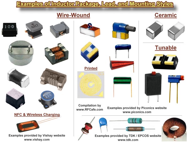
Inductor Package Styles
Inductors are passive devices used in electronic circuits to store energy in
the form of a magnetic field. They are the compliment of
capacitors, which store energy in the
form of an electric field. An ideal inductor is the equivalent of a short circuit
(0 ohms) for direct currents (DC), and presents an opposing force (reactance) to
alternating currents (AC) that depends on the frequency of the current. The reactance
(opposition to current flow) of an inductor is proportional to the frequency of
the current flowing through it. Inductors are sometimes referred to as "coils" because
most inductors are physically constructed of coiled sections of wire.
The property of inductance that opposes a change in current flow is exploited
for the purpose of preventing signals with a higher frequency component from passing
while allowing signals of lower frequency components to pass. This is why inductors
are sometimes referred to as "chokes," since they effectively choke off higher frequencies.
A common application of a choke is in a radio amplifier biasing circuit where the
collector of a transistor needs to be supplied with a DC voltage without allowing
the RF (radio frequency) signal from conducting back into the DC supply.
  When used in
series (left drawing) or
parallel (right drawing) with its circuit
compliment, a capacitor, the inductor-capacitor combination forms a circuit that
resonates at a particular frequency that depends on the values of each component.
In the series circuit, the impedance to current flow at the resonant frequency is
zero with ideal components. In the parallel circuit (right), impedance to current
flow is infinite with ideal components. When used in
series (left drawing) or
parallel (right drawing) with its circuit
compliment, a capacitor, the inductor-capacitor combination forms a circuit that
resonates at a particular frequency that depends on the values of each component.
In the series circuit, the impedance to current flow at the resonant frequency is
zero with ideal components. In the parallel circuit (right), impedance to current
flow is infinite with ideal components.
 Real-world inductors made of physical components
exhibit more than just a pure inductance when present in an AC circuit. A common
circuit simulator model is shown to the left. It includes the actual ideal inductor
with a parallel resistive component that responds to alternating current. The DC
resistive component is in series with the ideal inductor, and a capacitor is connected
across the entire assembly and represents the capacitance present due to the proximity
of the coil windings. SPICE-type simulators use this or an even more sophisticated
model to facilitate more accurate calculations over a wide range of frequencies. Real-world inductors made of physical components
exhibit more than just a pure inductance when present in an AC circuit. A common
circuit simulator model is shown to the left. It includes the actual ideal inductor
with a parallel resistive component that responds to alternating current. The DC
resistive component is in series with the ideal inductor, and a capacitor is connected
across the entire assembly and represents the capacitance present due to the proximity
of the coil windings. SPICE-type simulators use this or an even more sophisticated
model to facilitate more accurate calculations over a wide range of frequencies.
Related Pages on RF Cafe - Inductors &
Inductance Calculations
- Inductance Conversions -
Standard Inductor Values -
Inductor Vendors
The
HamWaves.com
website has a very sophisticated calculator for coil inductance that allows you
to en9ter the conductor diameter.
Equations (formulas) for combining inductors in series and parallel are given
below. Additional equations are given for inductors of various configurations.
Series-Connected Inductors

Total inductance of series-connected inductors is equal to the sum of the individual
inductances. Keep units constant.
Closely Wound Toroid
Rectangular Cross-Section
Coaxial Cable Inductance
Straight Wire Inductance
 These equations apply for
when the length of the wire is much longer than the wire diameter (look up
wire diameter here). The ARRL Handbook presents
the equation for units of inches and µF: These equations apply for
when the length of the wire is much longer than the wire diameter (look up
wire diameter here). The ARRL Handbook presents
the equation for units of inches and µF:
For lower frequencies - up through about VHF, use this formula:
Above VHF, skin effect causes the ¾ in the top equation to approach unity (1),
so use this equation:
Straight Wire Parallel to Ground Plane w/One End Grounded
The ARRL Handbook presents this equation for a straight wire suspended above
a ground plane, with one end grounded to the plane:

a = wire radius,
l = wire length parallel to ground plane
h = height of wire above ground plane to bottom of wire
Parallel Line Inductance
Multi-Layer Air-Core Inductance
Wheeler's
Formula: 
Parallel-Connected Inductors
Total inductance of parallel-connected inductors is equal to the reciprocal of
the sum of the reciprocals of the individual inductances. Keep units constant.
Inductance Formula Constants and Variables
The following physical constants and mechanical dimensional variables apply to
equations on this page. Units for equations are shown inside brackets at the end
of equations; e.g.,  means lengths
are in inches and inductance is in Henries. If no units are indicated, then any
may be used so long as they are consistent across all entities; i.e., all meters,
all µH, etc. means lengths
are in inches and inductance is in Henries. If no units are indicated, then any
may be used so long as they are consistent across all entities; i.e., all meters,
all µH, etc.
C = Capacitance
L = Inductance
N = Number of turns
W = Energy
εr = Relative permittivity (dimensionless)
ε0 = 8.85 x 10⁻¹² F/m (permittivity
of free space)
µr = Relative permeability (dimensionless)
µ0 = 4π
x 10-7 H/m (permeability of free space)
1 meter = 3.2808 feet <—> 1 foot = 0.3048 meters
1 mm = 0.03937 inches <—> 1 inch = 25.4 mm
Also, dots (not to be confused with decimal points)
are used to indicate multiplication in order to avoid ambiguity.
Inductive Reactance
Inductive reactance (XL, in Ω) is proportional to the frequency
(ω, in radians/sec, or f, in Hz) and inductance (L, in Henries). Pure inductance
has a phase angle of 90° (voltage leads current with a phase angle of 90°).
Energy Stored in an Inductor
Energy (W, in Joules) stored in an inductor is half the product of the inductance
(L, in Henries) and the current (I, in amp) through the device.
Voltage Across an Inductor
The inductor's property of opposing a change in current flow causes a counter
EMF (voltage) to form across its terminals opposite in polarity to the applied voltage.
Quality Factor of Inductor

Quality factor is the dimensionless ratio of reactance to resistance in an inductor.
Single-Layer Round Coil Inductance
Wheeler's
Formula for d >> a:
In general for a = wire radius:
Note: If lead lengths are significant, use the straight wire calculation to add
that inductance.
Wheeler's general
formula for a single layer coil is:
 , where dimensions are in cm. , where dimensions are in cm.
Finding the Equivalent "RQ"
 Since the "Q" of an inductor is the ratio of
the reactive component to the resistive component, an equivalent circuit can be
defined with a resistor in parallel with the inductor. This equation is valid only
at a single frequency, "f," and must be calculated for each frequency of interest. Since the "Q" of an inductor is the ratio of
the reactive component to the resistive component, an equivalent circuit can be
defined with a resistor in parallel with the inductor. This equation is valid only
at a single frequency, "f," and must be calculated for each frequency of interest.
|