Module 10 - Introduction to Wave Propagation, Transmission Lines, and Antennas
Pages i,
1-1,
1-11,
1-21,
1-31,
1-41,
2-1,
2-11,
2-21,
2-31,
2-40,
3-1,
3-11,
3-21,
3-31,
3-41,
3-51,
4-1,
4-11,
4-21,
4-31,
4-41,
4-51, Index
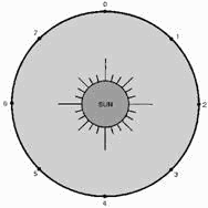
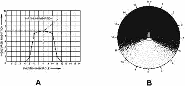
An ANIsotropic Radiator radiates energy directionally.
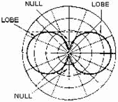
A LOBE is the area of a radiation pattern that is covered by radiation.
a NULL is the area of a radiation pattern that has minimum radiation.
4-51
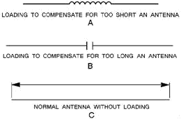
Antenna LoadING is the method used to change the electrical length of an antenna. This
keeps the antenna in resonance with the applied frequency. It is accomplished by inserting a variable inductor or
capacitor in series with the antenna.
A Half-WAVE Antenna (Hertz) consists of two lengths of rod or tubing, each a
quarter-wave long at a certain frequency, which radiates a doughnut pattern.
4-52
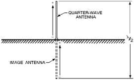
 A QUARTER-WAVE Antenna (Marconi) is a half-wave antenna cut in half with one end
grounded. The ground furnishes the missing half of the antenna.
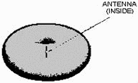
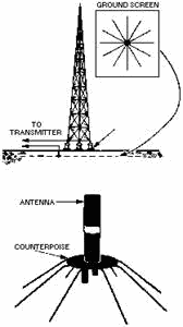
 The Ground SCREEN and the COUNTERPOIsE are used to reduce losses
caused by the ground in the immediate vicinity of the antenna. The ground screen is buried below the surface of
the earth. The counterpoise is installed above the ground.
4-53
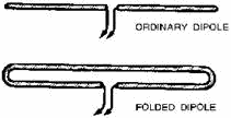
 The FOLDED DIPOLE consists of a dipole radiator, which is connected in parallel at its
ends to a half-wave radiator.
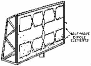
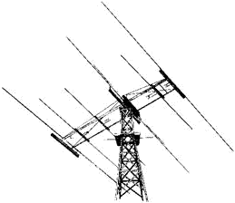
AN ARRAY is a combination of half-wave elements operating together as a single antenna.
It provides more gain and greater directivity than single element antennas. A DRIVEN ARRAY
derives its power directly from the source. A PARASITIC ARRAY derives its power by
coupling the energy from other elements of the antenna.
4-54
The BIDirectIONAL ARRAY radiates energy equally in two opposing directions. The
UNIDirectIONAL ARRAY radiates energy efficiently in a single direction. The
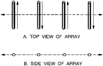
COLLINEAR ARRAY has elements in a straight line. Maximum radiation occurs at right angles to this line.
The BROADSIDE ARRAY has elements parallel and in the same plane. Maximum radiation develops in
the plane at right angles to the plane of the elements.
The END-FIRE ARRAY has elements parallel to each other and in the same plane. Maximum
radiation occurs along the axis of the array.
MATCHING STUBS are used between elements to maintain current in the proper phase.
The Gain of a COLLINEAR Antenna is greatest when the elements are spaced from 0.4 to 0.5
wavelength apart or when the number of elements is increased. The OPTIMUM Gain of a BROADSIDE
ARRAY
is obtained when the elements are spaced 0.65 wavelength apart.
4-55
A PARASITIC ARRAY consists of one or more parasitic elements with a driven element.
The amount of power gain and directivity depends on the lengths of the parasitic elements and the spacing between
them.
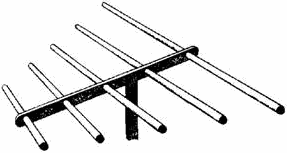
MULTIELEMENT ARRAYS, such as the YAGI, have a narrow frequency response as well as a
narrow beamwidth.
A Long-Wire Antenna is an antenna that is a wavelength or more long at the operating
frequency. These antennas have directive patterns that are sharp in both the horizontal and vertical planes.
4-56
BEVERAGE Antennas consist of a single wire that is two or more wavelengths long.
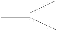
A V Antenna is a bi-directional antenna consisting of two horizontal, long wires
arranged to form a V.
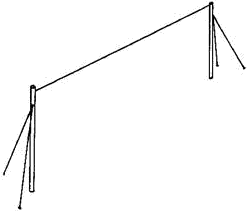
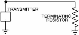
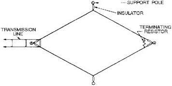
The RHOMBIC Antenna uses four conductors joined to form a rhombus shape. This antenna
has a wide frequency range, is easy to construct and maintain, and is noncritical as far as operation and
adjustment are concerned.
4-57
The TurnsTILE Antenna consists of two horizontal, half-wire antennas mounted at right
angles to each other.
Answers to Questions Q1. Through Q48. A1. Half-wave (Hertz) and quarter-wave (Marconi). A2. Coupling device, feeder, and antenna.
A3. Frequency of operation of the transmitter, amount of power to be radiated, and general direction of the
receiving set.
4-58
A4. One-half the wavelength. A5. Current and voltage loops.
A6. Current and voltage nodes. A7. Reciprocity of antennas. A8. Electric (E) field.
A9. Circular polarization. A10. Vertical polarization.
A11. Less interference is experienced by man-made noise sources. A12. Vertical polarization.
A13. 73 ohms. A14. Anisotropic radiator.
A15. Isotropic radiator. A16. Anisotropic radiator. A17. Dipole, doublet and Hertz.
A18. Nondirectional. A19. Vertical plane.
A20. The pattern would flatten. A21. To connect one end through a capacitor to the final output stage
of the transmitter. A22. a circular radiation pattern in the horizontal plane, or same as a half wave.
A23. It is composed of a series of conductors arranged in a radial pattern and buried 1 to 2 feet below the
ground. A24. Nine times the feed-point impedance. A25. Folded dipole. A26. To
produce desired phase relationship between connected elements. A27. Major lobes have the greatest amount
of radiation.
A28. Four. A29. As more elements are added, an unbalanced condition in the system occurs which impairs
efficiency. A30. By increasing the lengths of the elements of the array.
4-59
A31. Directivity increases. A32. Lower radiation resistance.
A33. Parallel and in the same plane. A34. They sharpen. A35. Extremely low radiation
resistance, confined to one frequency, and affected by atmospheric conditions.
A36. Along the major axis A37. Symmetrically. A38. Length of the parasitic element (tuning)
and spacing between the parasitic and driven elements. A39. Increased gain and directivity.
A40. Rotary array. A41. Their adjustment is critical and they do not operate over a wide frequency
range. A42. Increased gain.
A43. Multielement parasitic array. A44. One-half wavelength. A45. Wave antenna.
A46. Opposite. A47. It requires a large antenna site.
A48. For omnidirectional vhf communications.
4-60
| - |
Matter, Energy,
and Direct Current |
| - |
Alternating Current and Transformers |
| - |
Circuit Protection, Control, and Measurement |
| - |
Electrical Conductors, Wiring Techniques,
and Schematic Reading |
| - |
Generators and Motors |
| - |
Electronic Emission, Tubes, and Power Supplies |
| - |
Solid-State Devices and Power Supplies |
| - |
Amplifiers |
| - |
Wave-Generation and Wave-Shaping Circuits |
| - |
Wave Propagation, Transmission Lines, and
Antennas |
| - |
Microwave Principles |
| - |
Modulation Principles |
| - |
Introduction to Number Systems and Logic Circuits |
| - |
- Introduction to Microelectronics |
| - |
Principles of Synchros, Servos, and Gyros |
| - |
Introduction to Test Equipment |
| - |
Radio-Frequency Communications Principles |
| - |
Radar Principles |
| - |
The Technician's Handbook, Master Glossary |
| - |
Test Methods and Practices |
| - |
Introduction to Digital Computers |
| - |
Magnetic Recording |
| - |
Introduction to Fiber Optics |
| Note: Navy Electricity and Electronics Training
Series (NEETS) content is U.S. Navy property in the public domain. |
|


