NEETS Module 15 - Principles of Synchros, Servos, and Gyros
Pages i,
1-1,
1-11,
1-21,
1-31,
1-41,
1-51,
1-61,
1-71,
2-1,
2-11,
2-21,
2-31,
3-1,
3-11,
3-21,
4-1, Index
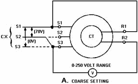
Figure 1-40A. - Zeroing a control transformer by the voltmeter method.
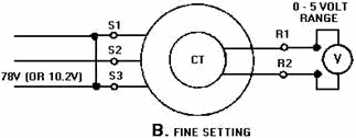
Figure 1-40B. - Zeroing a control transformer by the voltmeter method.
4. Deenergize the circuit, reconnect the S1, S2, and S3 leads back to their original positions, and then
connect the circuit as shown in view B. 5. Reenergize the circuit. Start with a high scale on the
meter and work down to the 0- to 5-volts scale to protect the meter movement. At the same time, turn the stator of
the CT to obtain a zero or minimum reading on the meter. Clamp down the CT stator, ensuring the reading does not
change. This is the fine electrical zero position of the CT. Zeroing Multispeed Synchro Systems.
If multispeed synchro systems are used to accurately transmit data, the synchros within the systems must be zeroed
together. This is necessary because these synchros require a common electrical zero to function properly in the
system.
First, establish the zero or reference position for the unit whose position the system transmits. Then, zero the
most significant synchro in the system first, working down to the least significant. For example, zero the coarse
synchro, then the medium synchro, and finally the fine synchro. When you zero those synchros, consider each
synchro as an individual unit and zero it accordingly.
1-51
Q-62. When is a synchro receiver (TR) properly zeroed? Q-63. What
should a voltmeter read when a TX is set on coarse zero? Q-64. What precaution should you take
when you use 115 volts to zero a differential? Q-65. Why should a synchro be rechecked for
zero after it is clamped down? Q-66. What is the output voltage of a CT when it is set on
electrical zero? Q-67. When you zero a multispeed synchro system which synchro should you zero
first? ELECTRICAL LOCK METHOD The electrical lock method, although not as
accurate as the voltmeter method, is perhaps tile fastest method of zeroing synchros. However, this method can be used only if the rotors of the units to be zeroed are free to turn and the lead connections are accessible. For
this reason, this method is usually used on the TR because, unlike transmitters, the TR shaft is free to turn.
To zero a synchro by the electrical lock method, deenergize the unit, connect the leads as shown in figure 1-41,
and apply power. The synchro rotor will then quickly snap to the electrical zero position and lock. If the
indicating device connected to the synchro shaft does not point to zero, loosen the synchro in its mounting and
rotate it until the zero position of the indicator corresponds with the electrical zero of the synchro. As we
stated previously, you may use 115 volts as the power source instead of 78 volts, provided you do not leave the
unit connected for more than 2 minutes.
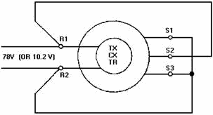
Figure 1-41. - Zeroing a synchro by the electrical lock method.
SYNCHRO TESTERS Two types of synchro testers are shown in figure 1-42, view (A) and
view (B). Each is nothing more than a synchro receiver on which a calibrated dial is mounted.
1-52
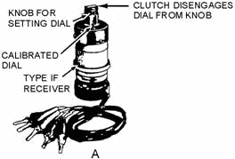
Figure 1-42A. - Synchro Testers.
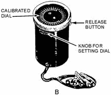
Figure 1-42B. - Synchro Testers.
These testers are used primarily for locating defective synchros. Although they do provide a method for zeroing
synchros, they should not be relied on without question. It is possible for the calibrated dial to slip from its
proper position, and since the dial is graduated only every 10º, it is difficult to read small angles with
accuracy. Therefore, the synchro tester method of zeroing synchros is potentially less accurate than those
previously described. To zero a TX, CX or TR using a synchro tester, use the following procedure: 1.
Connect the synchro tester as shown in figure 1-43.
1-53

Figure 1-43. - Zeroing a synchro using a synchro tester.
2. Set the unit whose position the TX or CX transmits accurately on zero or on its reference position. In
the case of the TR, set its rotor to zero or to its reference position. 3. Turn the stator of the
synchro being zeroed until the synchro tester dial reads 0º. The synchro is now approximately on electrically
zero.
4. Momentarily short S1 to S3 as shown. If the synchro tester dial moves when S1 is shorted to S3, the
synchro is not zeroed. Check the tester dial to ensure it has not slipped. If the tester dial has not slipped,
move the synchro stator until there is no movement when S1 and S3 are shorted. This is the electrical zero
position of the synchro being aligned. Q-68. What method of zeroing a synchro is perhaps the
fastest but NOT necessarily the most accurate? Q-69. What restrictions are placed on the use
of the electrical lock method?
Q-70. When you zero a synchro with a synchro tester, what is indicated by a jump in the synchro
tester's dial when the S1 and S3 leads are momentarily shorted?
TROUBLESHOOTING SYNCHRO Systems
One of your duties in the Navy is to keep the synchro systems in your equipment in good working order.
Therefore, it is essential that you become familiar with the details of synchro maintenance and repair.
First, let's consider some of the more common problem areas you should avoid when working with synchros. As with
any piece of electrical or electronic equipment, if it works - leave it alone. Do not attempt to zero a synchro
system that is already zeroed just because you want to practice. More often than not, the system will end up more
out of alignment than it was before you attempted to rezero it. Do not attempt to take a synchro apart, even if it
is defective. a synchro is a piece of precision equipment that requires special equipment and techniques for
disassembly. Disassembly should be done only by qualified technicians in authorized repair shops. a synchro,
unlike an electric motor, does not require periodic lubrication. Therefore, never attempt to lubricate a synchro.
Synchros also require careful handling. Never force a synchro into place, never use pliers on the threaded shaft,
and never force a gear or dial onto the shaft. Finally, never connect equipment that is not related to the synchro
system to the primary excitation bus. This will cause the system to show all the symptoms of a shorted rotor when
the equipment is turned on; but, the system will check out good when the equipment is off.
1-54
Trouble in a synchro system that has been in operation for some time is usually one of two types.
First, the interconnecting synchro wiring often passes through a number of switches; at these points opens,
shorts, or grounds may occur. You will be expected to trace down these troubles with an ohmmeter. You can find
an open easily by checking for continuity between two points. Similarly, you can find a ground by checking the
resistance between the suspected point and ground. a reading of zero ohms means that the point in question is
grounded. Secondly, the synchro itself may become defective, due to opens and shorts in the windings, bad
bearings, worn slip rings, or dirty brushes. You can do nothing about these defects except replace the synchro.
Troubles in new and modified synchro systems are most often because of (1) improper wiring and (2)
misalignment caused by synchros not being zeroed. You are responsible for finding and correcting these troubles.
You can check for improper wiring with an ohmmeter by making a point-to-point continuity and resistance check. You
can correct misalignment of a synchro system by rezeroing the entire system.
TROUBLE INDICATORS When trouble occurs in an electronic installation that contains a
large number of synchro systems, it may be very difficult to isolate the trouble to one particular system. Since
it is vital that maintenance personnel locate the point of trouble and fix it in as short a time as possible,
indicators, which aid in locating the trouble quickly, are included in the equipment. These indicators are usually
signal lights, mounted on a central control board and connected to the different synchro systems. When trouble
occurs in a synchro system, the signal light connected to it may either light or flash. Maintenance personnel
identify the defective system by reading the name or number adjacent to the light. Signal lights indicate
either overload conditions or blown fuses. Overload indicators are usually placed in the stator circuit of a
torque synchro system because the stator circuit gives a better indication of mechanical loading than does the
current in the rotor circuit. One version of this type of indicator, as shown in figure 1-44, consists of a neon
lamp connected across the stator leads of a synchro system by two transformers. The primaries, consisting of a few
turns of heavy wire, are in series with two of the stator leads; the secondaries, consisting of many turns of fine
wire, are in series with the lamp. The turns ratios are designed so that when excess current flows through the
stator windings, the neon lamp lights. For example, when the difference in rotor positions exceeds about 18º, the
lamp lights, indicating that the load on the motor shaft is excessive.

Figure 1-44. - Overload stator current indicator.
Blown fuse indicators are front panel lights which light when a protective fuse in series with the rotor blows.
Figure 1-45 shows a typical blown fuse indicator. If excessive current flows in the rotor windings of this circuit
because of a short or severe mechanical overload, one of the fuses will blow and the neon lamp across the fuse
will light.
1-55
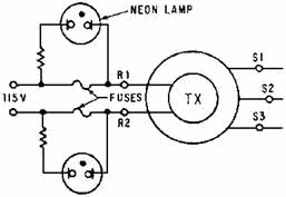
Figure 1-45. - Simple blown fuse indicator.
Another type of blown fuse indicator uses a small transformer having two identical primaries and a secondary
connected, as shown in figure 1-46. With both fuses closed, equal currents flow through the primaries. This
induces mutually canceling voltages in the secondary. If a fuse blows, the induced voltage from just one primary
is present in the secondary, and the lamp lights.
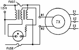
Figure 1-46. - Blown fuse indicator requiring only one lamp.
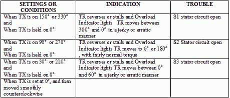
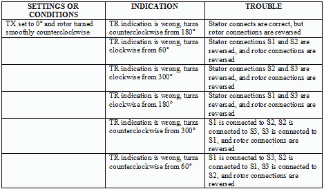
SYMPTOMS and CAUses To help the technician further isolate synchro problems, many
manufacturers furnish tables of trouble symptoms and probable causes with their equipment. These tables are a
valuable aid in isolating trouble areas quickly. Tables 1-2 through 1-7 summarize, for a simple TX-TR system, some
typical trouble symptoms and their probable causes. Keep in mind, if two or more receivers are connected to one
transmitter, similar symptoms occur. However, if all the receivers act up, the trouble is usually in the
transmitter or main bus. If the trouble appears in one receiver only, check the unit and its connections.
1-56
The angles shown in these tables do not apply to systems using differentials, or to systems whose units
are incorrectly zeroed.
Table 1-2. - General Symptoms
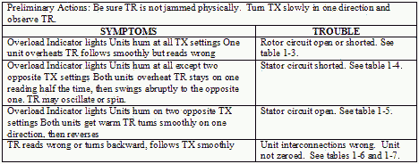
Table 1-3. - Open or Shorted Rotor

1-57
Table 1-4. - Shorted Stator
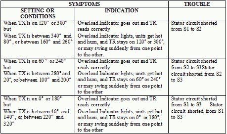
Table 1-5. - Open Stator
1-58
Table 1-6. - Wrong Stator Connections, Rotor Wiring Correct
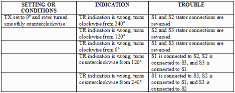
Table 1-7. - Wrong Stator and/or Reversed Rotor Connections
In a control system, the trouble may be slightly more difficult to isolate. However, the existence of trouble
is readily indicated when the system does not properly respond to an input order. For control systems, it is
easier to locate the trouble by using a synchro tester or by checking the operating voltages.
1-59
Voltage TESTING Another good way to isolate the trouble in an operating
synchro system is to use known operating voltages as references for faulty operation. Since the proper operation
of a system is indicated by specific rotor and stator voltages, an ac voltmeter can be used to locate the trouble.
When an ac voltmeter is connected between any two stator leads, the voltage should vary from 0 to 90 volts (0 to
11.8 volts for 26- volt systems) as the transmitter rotates. The zero and maximum voltage values should occur at
the following headings:

The rotor voltage should remain constant at all times, either 115 volts or 26 volts. In a system where the
units are close enough to permit checking, the voltage between the R1 and R2 terminal of any unit energized by the
primary ac source and the corresponding R1 or R2 terminal of any other unit energized by the primary ac source
should be zero. When the excitation voltage (115 volts or 26 volts) is above or below the nominal value, the
maximum stator voltages will also be above or below normal. SYNCHRO TESTERS
Synchro testers, as stated earlier, are used primarily for quickly locating a defective synchro. These testers are
capable of functioning as either transmitter or receiver. When a transmitter is suspected of being
defective, a synchro tester is usually substituted in its place to simulate its actions. When the tester is used
in this manner, a braking arrangement on the tester applies the necessary friction to hold its shaft in different
positions so you can determine whether the transmitter is good or bad. When using the tester as a transmitter, it
is usually a good idea to use only one receiver so as not to overload the tester. If the tester is connected in
place of a TR or used to check the output of a transmitter, the brake is released, allowing the rotor to turn and
indicate the transmitter's position. By observing the tester's response to the transmitted signal, you can
determine if the TR is defective or if the transmitter's output is incorrect. Q-71. What
should you do with a synchro that has a bad set of bearings?
Q-72. Name two types of trouble you would expect to find in a newly installed synchro system.
Q-73. What type of indicator is usually placed in the stator circuit of a torque synchro system?
Q-74. What is the most probable cause of trouble in a synchro system that has all of its receivers
reading incorrectly? Q-75. If an ac voltmeter is connected between the S2 and S3 windings on a
TX, at what two rotor positions should the voltmeter read maximum voltage? Q-76. What
precaution should you take when substituting a synchro tester in a circuit for a transmitter?
1-60
| - |
Matter, Energy,
and Direct Current |
| - |
Alternating Current and Transformers |
| - |
Circuit Protection, Control, and Measurement |
| - |
Electrical Conductors, Wiring Techniques,
and Schematic Reading |
| - |
Generators and Motors |
| - |
Electronic Emission, Tubes, and Power Supplies |
| - |
Solid-State Devices and Power Supplies |
| - |
Amplifiers |
| - |
Wave-Generation and Wave-Shaping Circuits |
| - |
Wave Propagation, Transmission Lines, and
Antennas |
| - |
Microwave Principles |
| - |
Modulation Principles |
| - |
Introduction to Number Systems and Logic Circuits |
| - |
- Introduction to Microelectronics |
| - |
Principles of Synchros, Servos, and Gyros |
| - |
Introduction to Test Equipment |
| - |
Radio-Frequency Communications Principles |
| - |
Radar Principles |
| - |
The Technician's Handbook, Master Glossary |
| - |
Test Methods and Practices |
| - |
Introduction to Digital Computers |
| - |
Magnetic Recording |
| - |
Introduction to Fiber Optics |
| Note: Navy Electricity and Electronics Training
Series (NEETS) content is U.S. Navy property in the public domain. |
|


