|
July 1969 Electronics World
 Table of Contents
Wax nostalgic about and learn from the history of early electronics. See articles
from
Electronics World, published May 1959
- December 1971. All copyrights hereby acknowledged.
|
This is Part 3 of a 3-part series
of articles on atomic radiation that appeared in Electronic World magazine in
1969. It deals with measurement techniques and equipment.
Shippingport Atomic Power Station, the first full scale nuclear power
plant in the United Sates, went operational in 1957. It marked the dawn of a new era
of electric power generation that was filled with grandiose predictions of limitless,
non-polluting, dirt cheap power. Everything was going to be powered by electricity -
air heating and cooling, lighting, automobiles, refrigeration, cooking, water heating.
Atomic power was going to be a figurative and almost literal
beating
of swords into ploughshares as the destructive energy of nuclear weapons was put
to use in powering the world. People were still getting used to the concept of being
a nuclear citizen and wanted to be educated on the subject. Many articles such as this
one appeared in every sort of magazine from Electronics World to The Saturday
Evening Post.
Author Joseph Wujek published a 3-part article in Electronics World in 1969 to address
the issues. Here is Part 1 -
Types & Relationships,
Part 2 - Detection Methods,
and Part 3 - Measuring
Techniques.
Part 3. An examination of the basic circuits that are used in spectroscopy
to measure accurately the amount of radiation.

Hewlett-Packard developed this nuclear counting system. Radioactive
samples in trays (right) are automatically selected and monitored. The level of radiation
is shown by lighted numbers on the scaler console and by punched paper tape.
By Joseph H. Wujek, Jr.
Before examining some of the circuits and systems used in radiation measurement, we
should state the design goal of an ideal radiation measurement system.
Ideally, a radiation measuring system should detect the presence of radiation, identify
the types of radioactive particles, and measure the flux level (number of particles per
unit area in a given time period). The last function - sorting out the number of particles
of a particular energy over a given time interval, is called "obtaining a spectrum of
the radiation, or "performing pulse-height analysis." Of course, there may be additional
design goals. We may require that the system perform calculations, such as averaging
particle counts over a given time period and to display and/or print out these results.
We may also require
the system to sound an audible and/or visual alarm when thee radiation level exceeds
some predetermined level. Too, we may require a very high resolution system, so that
small energy differences between particles can be realized. There may also be a requirement
to measure very low energy particles existing in the presence of high "natural" or "background"
radiation, thus demanding a low-noise system with good background rejection. And, finally,
the system may require a high degree of measurement precision, that is, a system which
remains stable over a long time period regardless of use, variations in ambient temperature,
or power-supply voltages. Clearly, every measurement system does not require all of these
refinements. But most systems encountered in nuclear spectroscopy are designed with these
considerations in mind.
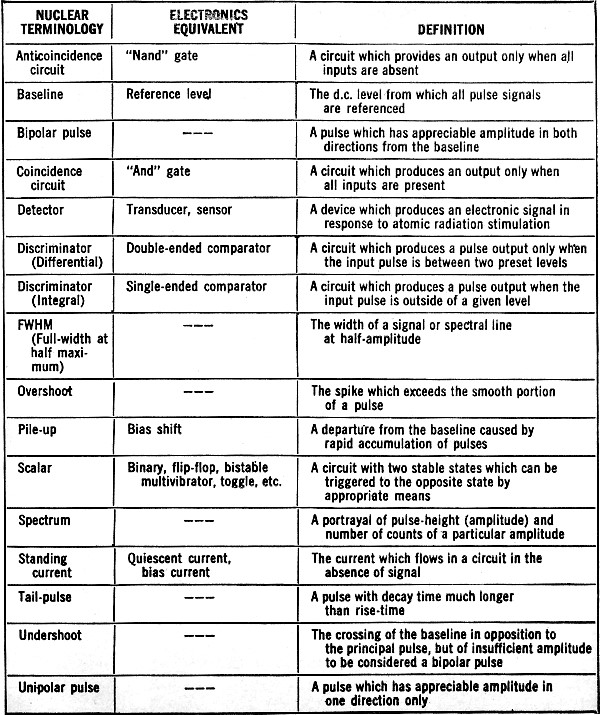
Language of Nuclear Instrumentation

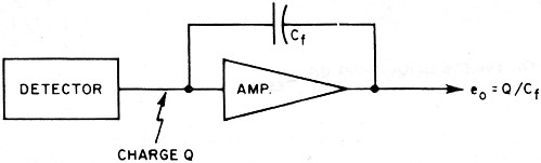
Fig. 1 - Charge amplifier circuits must have high open-loop gain.

Fig. 2 - Some common pulse-shaping networks. (A) is a simple RC differentiator,
while (B) and (C) are idealized single and double delay-line shapers. (Z0
is characteristic impedance.)

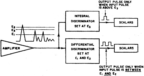
Fig. 3 - Block diagram of a simple pulse-height analyzer.
Unfortunately, many engineers in the nuclear instrumentation field use jargon or some
words which are completely foreign to other areas of electronics. A good example is found
in the expression "full-width at half-maximum." This rather verbose statement is simply
a measure of the sharpness of a spectral line and hence is not very different from the
"Q" used elsewhere in electronics. Other examples of this unique and sometimes cumbersome
language is the scalar (flip-flop or bistable multivibrator) and the coincidence gate
(and gate). Because workers in the industry persist in using this terminology, we offer
a short glossary in Table 1 to aid the newcomer to the field. More formal and extensive
definitions may be found in the "Standards of the Institute of Electrical and Electronics
Engineers for Nuclear Science."
Radiation Detector Circuits
All radiation detectors used in spectroscopy require some kind of amplifier. Fig.
1 is a simple amplifier used to provide "charge" amplification. In Part:2 ("Atomic Radiation:
Detection Methods"), we showed why the capacitance of some detectors is dependent upon
certain bias conditions and why it is advantageous to measure the charge deposited by
an incident particle rather than to measure a voltage change.
If the circuit in Fig. 1 is treated as an operational amplifier, certain simplifying
assumptions can be made. They are: the amplifier has high open-loop input impedance and
high open-loop voltage gain. Thus. eo = Q/Cf. This same circuit
is used to perform the integration operation in analog signal processing. Again, if we
assume the feedback capacitor Cf is a stable element, the output voltage is
proportional to the charge generated by the detector. In most commercially available
systems, temperature stabilities of better than 0.01% per degree C and voltage gains
of 10 to 100 are common.
Resolution and threshold is detector limited, not electronically limited. In fact,
circuit development has kept pace with detectors. Preamplifiers using FET input stages
and solid-state detectors can be operated at very low temperatures, thus reducing system
noise. (Most noise sources are strongly temperature dependent.) Bipolar transistors used
in earlier systems exhibited considerable gain degradation at low temperature but FET
devices do not, thus the FET system also improves over-all performance.
Systems have been operated at temperatures near liquid nitrogen with good results.
The boiling point of liquid nitrogen is about 320° below zero F. At these temperatures
there is relatively little thermal energy in the atoms within the crystal lattices, hence,
little noise.
In addition, amplifiers used in radiation detecting instruments must be capable of
fast recovery. Often, input signals several hundred times the input pulse amplitude occur,
sufficient to saturate the output. These pulses severely overload the output. But, a
recovery time of several microseconds is indicative of the state-of-the-art.
Pulse-shaping is an important consideration in establishing over-all system performance.
Linearity, time-resolution, noise, overload recovery, and over-all precision are affected
by the pulse-shaping network.

Table 1. A glossary of terms used in nuclear electronics system technology.
Perhaps the most commonly employed pulse-shaper is the simple RC-differentiator, often
used in pulse work as well as linear circuits. Fig. 2 shows the RC pulse-shaper along
with two of the more common schemes for shaping which employ delay lines. The various
trade-off's, which determine which scheme is "best" for a given application, will not
be discussed here, except to note that the choice is often dictated by system restraints.
Discriminators find widespread use in nuclear systems. Within the context of the present
discussion, a discriminator is a circuit which changes its output state when prescribed
conditions are fulfilled at the input. An integral discriminator is a circuit which changes
state and remains in that state, as long as the input is above (or below) a given voltage.
A differential discriminator changes output state as long as the input remains between
two given voltage levels. This voltage difference between these levels is commonly called
the "window." In the more descriptive language of digital circuits, the integral and
differential discriminators are, respectively, termed single-ended and double-ended differential
voltage comparators.
The discriminator finds use in pulse-height analysis of the output of detector amplifiers.
An array of these circuits can be used to route an output pulse to a particular counting
channel, as shown in Fig. 3. Scalars, or other means, are used to count the number of
pulses of each particular energy band (energy is proportional to pulse height), thus
generating a spectrum (Fig. 4). Commercial pulse-height analyzers are available which
show the spectrum on a CRT face, print out the number of counts in a given energy channel
(band), and otherwise gather data from a pulse-height source. Systems of 1024 channels
and more are available "off-the-shelf."
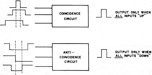
Coincidence and anticoincidence circuits (Fig. 5) form another basic building block
in nuclear detection systems. A coincidence circuit yields an output, if and only if,
two or more inputs signals are simultaneously present. The familiar and gate is an example
of a coincidence circuit. The anticoincidence circuit provides an output whenever signals
are not present at the same instant. This function is also readily implemented with familiar
digital circuits. Sophisticated coincidence and anticoincidence systems have been built
which can resolve events occurring fractions of a nanosecond apart. Since many atomic
reactions occur in sub-nanosecond times, these systems are extremely useful to the nuclear
physicist.
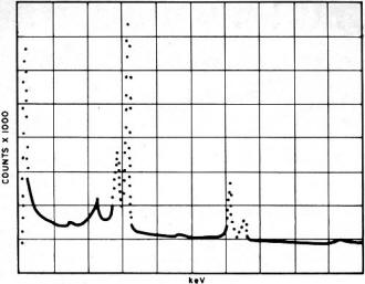
Fig. 4 - Spectrum of selenium-75 (Se-75). Spectrum is shown peaking
at 66, 81, 97, 121, 136, 199, 265, 280, 305, and 402 keV.

Fig. 5 - Similar to an "and" gate, circuits like these are used to
resolve events occurring a fraction of a nanosecond apart.
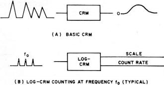
Fig. 6 - In the basic CRM (A), the output voltage is proportional
to the input pulse frequency. In the log CRM (B), the average signal rate fo
is represented at the output by a count rate voltage (0.5 Vd.c.) and a scale voltage
(1.0 Vd.c.). If the input rate is doubled, the scale voltage rises 10 2 volts d.c.

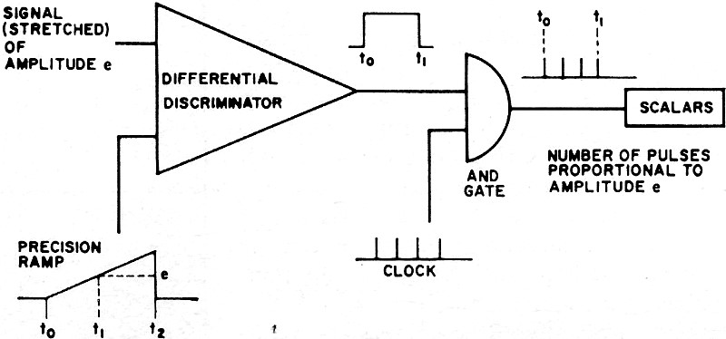
Fig. 7 - Elementary analog-to-digital converter is shown below.
The count-rate meter (CRM), which may or may not have a meter associated with it,
is another useful circuit. The CRM, by the nature of its design, is at best a 1% instrument
in terms of precision. In many applications, however, 1% is more than adequate.
The CRM is primarily an integrator and produces a voltage (or current) proportional
to the rate at which pulses are applied at its input. In performing this function, the
CRM is not unlike the pulse demodulator or the amplitude detector in an AM radio. Fig.
6 shows the principles involved in CRM circuitry.
So-called logarithmic count-rate meters have been built in a variety of configurations.
One type employs a logarithmic ("log") amplifier as a stage. Others feature "scale change"
circuits which automatically sense and change scale when the count rate goes outside
the limits of the CRM scale in use at the time interval in question. Dynamic ranges of
105 and more can be fashioned in this way.
The availability and low cost of digital integrated circuits and associated readouts
have tended to displace the CRM. However, narrow bandwidth requirements, small size,
low power requirements, and circuit simplicity considerations tend to offset the digital
circuit advantages in favor of the CRM. Remote sensing, as in space experiments, may
impose severe restrictions on the number of available data lines, again favoring the
CRM. In field instruments and certain special applications, the count-rate meter remains
an important design.
One other system is worth noting because of its widespread use in nuclear instrumentation.
The analog-to-digital converter (ADC), long used in computers, is used extensively in
counting systems. Many varieties of ADC's exist, but most have in common the gating of
a precision frequency. Fig. 7 shows the elements of a simple ADC. An integral discriminator
compares the amplitude of the incoming pulse (stretched for a time period compatible
with the conversion time) with a ramp voltage of precisely controlled length and amplitude.
When the ramp begins, pulses of known frequency are gated into a scalar chain. When the
ramp voltage reaches the voltage of the pulse, the pulses are gated off by the action
of the discriminator (comparator). The number of pulses stored in the scalar chain is
thus proportional to the amplitude of the signal. The ADC is then reset and awaits the
next incoming signal for a repeat of the cycle.
In practice, ADC's have been built with clock rates of 100 MHz and more, and conversion
times of fractions of a microsecond. The precision of the conversion is proportional
to the number of digital bits (flip-flops used) and hence, in the scheme just outlined,
the time of conversion. Thus, if we had six scalars and a 10-MHz clock, conversion could
take as long as 6.3 μs. This is found by taking 26 - 1 = 63, the bit storage
and multiplying by the clock rate of 100 ns. Other schemes, some rather elaborate, improve
upon this basic time conversion and precision limitation.
In addition, the somewhat unique (unique to nuclear work) applications of the circuits
already described, nuclear instrumentation systems make use of a variety of hardware
common to the electronic art. Core memories, X-Y plotters, CRT outputs, digital printers,
to name just a few, are often an integral part of a nuclear counting system. Direct interfacing
with computers is becoming commonplace, enabling the scientist to escape much of the
routine work of experimentation and data reduction. Improvements in detectors, especially
in low-noise detectors, enable the experimenter to perform measurements which were beyond
the state-of-the-art only months earlier. As with so much in modern science and technology,
electronics holds the key to new discoveries.
Posted February 15, 2018
|