|
June 1969 Electronics World
 Table of Contents
Wax nostalgic about and learn from the history of early electronics. See articles
from
Electronics World, published May 1959
- December 1971. All copyrights hereby acknowledged.
|
This is Part 2 of a 3-part series of articles on
atomic radiation that appeared in Electronics World magazine in 1969. The
first part, which dealt with various types of radiation and how they interacted with
matter, was posted a week or so ago. For instance ionizing versus nonionizing radiation,
where the former can cause cancer, the latter just burns you. This installment discuses methods
and equipment for detecting and measuring radiation levels. Ionizing radiation
detectors rely on having massive particles impinge on gas, solid, or liquid media and
causing a reaction that is visible or measurable by electronic means. Nowadays there
are highly sensitive and accurate solid state devices to replace the technology shown
here.
Author Joseph Wujek published a 3-part article in Electronics World in 1969 to address
the issues. Here is Part 1 -
Types & Relationships,
Part 2 - Detection Methods,
and Part 3 - Measuring
Techniques.
Atomic Radiation: Detection Methods
By Joseph H. Wujek, Jr.
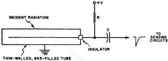
Fig. 1 - An elementary gas-filled detector. The output is dependent
on potential between electrodes, and gas pressure.
Part 2. You can't see it, and you probably won't know it's around until too late.
But here's what you use to detect presence of dangerous radioactivity.
(Editor's Note: In Part 1 of this series, we introduced some of the elementary concepts
of atomic radiation and discussed the basic units used to measure nuclear emanations.
This article examines nuclear detection methods and equipment.)
Nuclear radiation is detectable because the radioactivity interacts with matter. Charged
particles (α-particles, β-rays, etc.) interact with matter by ionizing the atoms as
the radiation passes through. Each ionization uses up to 50 eV of energy, depending upon
the element being irradiated. Hence, the number of electrons "knocked loose" (atoms ionized)
is a measure of the energy of the incident particle. For silicon, the ionization energy
is 3.5 eV; for germanium, 2.8 eV. This is the energy required to produce one ion/electron
pair. For a gas mixture of 90% argon and 10% methane, the energy loss is 25 eV. In gases,
some of the energy is used in the disassociation (breaking up) of the gas molecules.
Neutral particles (neutrons) interact with matter in a manner analogous to billiard-ball
collisions. Here the "billiard balls" are the nuclei of matter and the incoming neutron
particle. The recoiling nucleus interacts with other nuclei to produce electron/ion pairs.
In the case of gamma (r) radiation, incident energy either ionizes the atom, excites
an electron into a higher energy condition, or interacts with an atom to produce an electron
and a positron (positive electron). Electrons which are initially ionized can also ionize
other atoms, giving rise to secondary electrons.
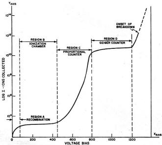
Fig. 2 - The response of the hypothetical detector shown in Fig. 1
for a given radiation and gas pressure. See text.
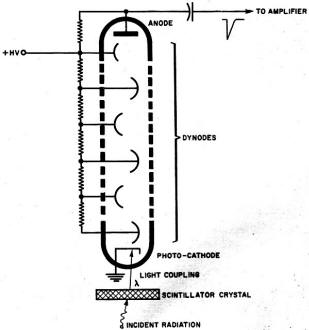
Fig. 3 - Scintillator crystal and photo-multiplier tube as used in
scintillator counter to detect electron excitation.
Hence in any of the mechanisms just outlined, the final result of the interactions
is the production of electrons. With this in mind, we now turn to an examination of the
principal types of nuclear radiation detectors used to exploit this phenomenon.
Gas-Filled Detectors
Perhaps the simplest radiation detector is an electric field between two surfaces.
Generally, the surfaces are concentric, and if a thin wire is used as the center conductor
and a thin-walled cylinder as the other electrode, the device is as shown in Fig. 1.
Depending on the potential difference (voltage bias) between the electrodes, and the
nature and pressure of the gas between them, several different types of detectors can
be made.
Fig. 2 shows several distinct regions of operation of this primitive detector. On
the Y axis, the number of ions collected (note the logarithmic scale) is plotted as a
function of bias voltage. Depending on the type of radiation, several curves can be drawn,
each characteristic of the incident radiation. While examining in detail the various
regions shown in Fig. 2, the nature of the interaction between the incoming radiation
and the gas molecules must be considered.
The steep portion of the curve marked "Region A" is not generally useful as a detector.
In this region the bias voltage is not high enough to collect the majority of ions and
electrons (ions to cathode, electrons to anode) before recombination occurs. Recombination
is the opposite of ionization, that is, electrons and ions unite to form an uncharged
atom.
As the bias voltage is increased, the ions and electrons are swept to the electrodes
at an increasing velocity and rate, and thus there is less time for recombination to
occur.
Further bias increase causes the detector to operate in the ionization region, creating
an ionization chamber, shown by "Region B" of the diagram. These detectors are normally
operated at pressures of up to 50 pounds per square inch and have a bias of several hundred
volts. These conditions allow efficient collection of the ions/electrons, but the energy
imparted to the particles by the bias is not high enough to generate secondary ions and
electrons. The output current of the ionization chamber is directly related to the total
energy of the particles which arrive over a given time interval. Since one ampere is
one coulomb of charge flowing in one second, for a constant current I flowing over time
T, the total charge is Q = I X T. Then at either electrode the charge collected is just ±Ne,
where N is the number of particles and e is the charge on the electron (1.6 X 10⁻¹⁹
coulomb). The appropriate sign (±) is taken at the electrode of interest.
To gain an insight into the level of the signals we expect to exist under these conditions,
assume that 106 ion/electron pairs are collected in one microsecond (10-6
second). Then if a rectangular pulse of current I exists, I = (Q/T) = (Ne/T), thus, I
= (106 X 1.6 X 10-19)/10-6 = 1.6 X 10⁻⁷ A
or 0.16 microamp. The equation ν = Q/C is used to find the amplitude of the voltage
pulse. If C is 100 pF (the total capacitance of the system), then ν = (1.6 X 10-19
X 106)/10-10 = 1.6 X 10⁻³ volt or 1.6 millivolts. Hence,
we see that signal levels are very low, even for a million (106) electrons
arriving in one microsecond. These low-level signals are difficult to amplify and process
in the presence of noise.
Another distinct disadvantage of the ionization chamber is that particle identity
(α, β, γ, etc.) cannot be determined, nor can the energy of a particle
be resolved. We have only a measure of the total incident particle energy.
The next region of interest occurs when the bias is raised high enough to produce
secondary electrons/ions. The number of secondary particles generated is proportional
to the bias voltage, hence "Region C" is termed the proportional region and a detector
which operates in the region is called a proportional counter.

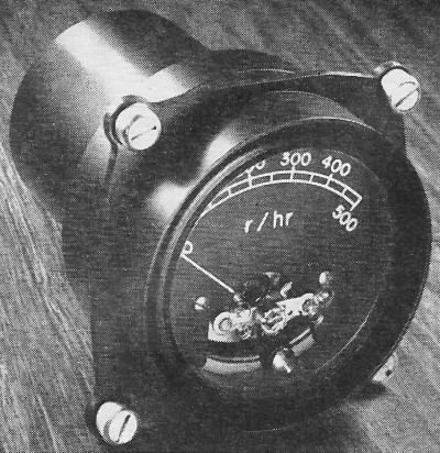
This Eberline & Associates meter is used in systems where it is
necessary to continuously monitor high radiation levels.
A proportional counter is a considerable improvement over the ionization chamber in
that the amplitude of the output pulse is proportional to the energy of the incoming
radiation which caused the pulse. Hence, energy-sorting or pulse-height analysis can
be performed. By means of appropriate particle shielding, the radiation which finally
"sees" the detector can be of a particular type. For example, it's easy to shield against α
and β particles, leaving only x-rays and γ-rays to be detected. Notice also
that the number of particles collected has increased several decades over the number
collected in the ionization region. Thus, signal processing becomes less of a problem
due to the increase in amplitude of the detector output.
The last region of interest, "Region D", is the Geiger region. This is the region
where the Geiger tube or Geiger-Mueller (G-M) detector, used by many prospectors and
radiation safety personnel, operates. In the G-M detector, a discharge occurs between
electrodes when a stream of ions/electrons bridges the inter-electrode gap. These pulse
are rather long in duration, but the addition of a "quench" gas can shorten the pulse
length to tens of μsec. However, at high counting rates the G-M detector is useless.
As with the ionization chamber, no energy sorting or particle identification is possible,
although α and β particles may be distinguished by the use of shields. The
G-M counter is popular because it furnishes a gross measure of radiation level and only
simple circuitry is needed to monitor the tube output. These devices can be built to
withstand rugged use in the field and are relatively inexpensive as compared to the more
sophisticated detection devices.
The Scintillator PM Tube
Certain materials exhibit an interesting and useful property when exposed to radiation.
In some materials, incoming radiation excites electrons to new energy states within the
atom. When the electrons return to their original energy state, the absorbed energy is
converted to a pulse of light. These pulses may last only a fraction of a nanosecond
or as long as a few milliseconds, depending upon the material. The material is said to
"scintillate" and the material is a scintillator. In theory, at least, we should be able
to "see" the excitation of an individual electron, but of course the light energy emitted
is at an extremely low level. In order to amplify the light and at the same time convert
the light energy into electrical energy, a photomultiplier (PM) tube is employed.
Fig. 3 illustrates the arrangement of the scintillator and PM tube. The PM tube consists
of a photo-cathode and a series of electrodes called dynodes, usually tied together by
a resistance divider as shown. When the light emitted by the scintillator strikes the
cathode, electrons are "kicked out" from the cathode by the photoelectric effect. Since
the first dynode is more positive than the cathode, it attracts the electrons. Upon impact
with the first dynode, additional electrons are generated which head toward the second
dynode. This action continues from dynode to dynode due to the increase in electron energy
caused by the potential difference between the successive electrodes. Hence, a multiplying,
or avalanche, effect (of electrons) is created as the stream proceeds. At the final dynode,
or anode, the resulting current pulse is coupled to the detector circuitry. The net effect
is to multiply the electrons and achieve a current gain of 107 or more. It
requires several tens of nanoseconds for the electron to traverse a PM tube.
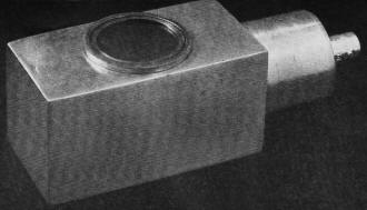
A typical proportional counter made by LND, Inc. Radioactive particles
entering the circular window ionize the atoms of a gas to give an output that is proportional
to the tube's voltage.
The scintillator/PM tube output pulse is proportional to energy, hence pulse-height
analysis may be performed. The resolving time of these detectors depends upon the time
required for the light pulse to decay after excitation. This decay time varies from less
than 10 nanoseconds for a stilbene crystal to about 0.2 microsecond for a sodium-iodide
scintillator. A wide variety of scintillator crystals are used in nuclear detection work,
the principal parameters of interest being the decay time and the sensitivity to incoming
particles. As in any of the detectors we have discussed, noise is also a fundamental
limitation of the useful range of the device.
Solid-State Detectors
The solid-state detector may be thought of as an ionizing device where the ionization
medium is a crystal lattice rather than a gas as was the case with the detectors of Figs.
1 and 2. As previously noted, the ionization energy for silicon and germanium is 3.5
eV and 2.8 eV, respectively.
Several important types of solid-state detectors are in use: diffused-junction, surface-barrier,
lithium-drifted, and totally depleted junction, among them.
Although important differences exist in the physics and technology of the four device
types mentioned, some similarities are also present. Each of the devices has, as the
principal means of detection, a p-n semiconductor junction that is operated under reverse
bias. Incoming radioactive particles produce ion/electron pairs in proportion to the
energy of the particles and the physical constants of the material.
The diffused-junction detector is not unlike a diffused-junction semiconductor diode,
although an optimum design of large surface area (hence more sensitivity) vs low capacitance
is the ideal. These detectors have a sensitive region and capacitance which is strongly
voltage-dependent, therefore a charge amplifier is used as the detector's first stage
rather than the usual voltage amplifier.
The surface-barrier detector has a very thin sensitive region upon which a thin-film
metallic (usually gold) electrode is deposited. The carriers may be thought to reside
principally at the interface between the gold layer and the crystal. Like the diffused-junction
device, capacitance is strongly dependent upon bias voltage.
Fig. 4 - (A) Gamma radiation from a cesium-137 sample peaks at 662
keV. Sodium-iodide scintillator with a PM tube is used. (B) Better resolution is obtained
when a lithium-drifted germanium detector at 770 K is used. The samples are the same.
If lithium ions are present in the semiconductor material it is possible to fabricate
detectors having a sensitive region far thicker than the diffused-junction (DJ) or surface-barrier
(SB) types. The capacitance of a lithium-drift device is nearly independent of bias voltage.
This permits use of a voltage amplifier as the input stage.
The extra thickness of sensitive region of the lithium-drift device permits its use
as a detector of higher energy particles than the DJ or SB types. With thin sensitive
regions, high-energy particles have a high probability of passing through a zone without
interacting with the crystal. This is analogous to throwing a small ball through a chicken-wire
fence. If a single thickness of wire fence is used, the chance of hitting the fence is
smaller than if several unaligned layers were used.
The totally depleted detector has a thick sensitive region and makes use of any or
all of the three technologies previously outlined. These detectors are inherently lower
in noise and generally faster in output rise-time than the DJ, SB, or lithium-drift types.
The totally depleted device will exhibit higher capacitance than the other three types,
although C is largely independent of voltage.
The solid-state detectors discussed will yield rise times from less than 10 nsec to
several hundred nanoseconds, depending upon the material, geometry, and type of device.
Circuits are often the limiter, rather than the detector. Frequency response, noise,
and input sensitivity can also limit the value of high-quality detectors (see Fig. 4).
Other Detectors
The calorimeter is an instrument for measuring heat rise and may be used to measure
radiation. In high-energy, high-flux levels, radiation will cause materials to heat.
Energy sorting may be accomplished by collimators and/or shielding. The temperature rise
of the calorimeter may be measured by monitoring resistance change with temperature,
or by using thermocouple junctions. One form of collimator consists of a narrow slit
milled through shielding material. Particles of a wavelength equal to the slit are passed,
others are blocked.
The spark-chamber consists of parallel electrodes maintained at several hundred volts'
potential. An incoming particle causes gas ionization in its path, triggering a spark.
Photographs furnish the record of direction and the length of the spark path is a measure
of the particle energy.
Other schemes, some of which are non-electronic in nature, exist for the detection
of nuclear radiation. The most important devices have been discussed in this article.
In the final article, we will discuss some of the circuits and systems used to process
the signals generated by these detectors.
(Concluded Next Month)
Posted January 22, 2018
|