|
August 1962 Electronics World
 Table of Contents
Wax nostalgic about and learn from the history of early electronics. See articles
from
Electronics World, published May 1959
- December 1971. All copyrights hereby acknowledged.
|
The nuvistor triode amplifier,
a component largely unknown to most people, even during its brief heyday in the
late 1950s through the early 1960s, was an attempt to bridge the technology gap
between the sunsetting of vacuum tubes and solid state transistors. Its relatively
low noise figure, small size, ruggedness, metal shield, and higher operating frequency
(near a gigahertz) were the main marketing features when RCA introduced the nuvistor
in 1959. Although adopted enthusiastically by many aware of its existence, the nuvistor,
as pointed out in this 1962 Electronics World article, tended to oscillate
if its metal body was not adequately grounded. You might expect the schematics included
in the article to explicitly show a ground connection to the can, but that is not
the case. Ultimately, a quick adoption of transistors by industry and hobbyists,
with their rapidly improving specifications and decreasing price, rendered the nuvistor
to the dustbin of electronic history.
 A nuvistor was used in the front end of the
HP3400A True RMS Voltmeter (thanks to Michael M. for that).
Also, thanks to Bob Davis for pointing out that the Lafayette
HB-400 CB radio sported a Nuvistor in the receiver front end.
Here is a Nuvistor
info resource. See the "Nuvistors and Micro-Modules," "The Tube Family Tree,"
"Lafayette
Radio Electronics," "Hitachi
Nuvistor Ad," "Using
the Nuvistor on V.H.F. Bands," and the "The NASA 136"
articles, too.
A nuvistor was used in the front end of the
HP3400A True RMS Voltmeter (thanks to Michael M. for that).
Also, thanks to Bob Davis for pointing out that the Lafayette
HB-400 CB radio sported a Nuvistor in the receiver front end.
Here is a Nuvistor
info resource. See the "Nuvistors and Micro-Modules," "The Tube Family Tree,"
"Lafayette
Radio Electronics," "Hitachi
Nuvistor Ad," "Using
the Nuvistor on V.H.F. Bands," and the "The NASA 136"
articles, too.
Using
the Nuvistor on V.H.F. Bands
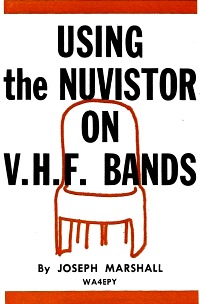
Results of experiences with this new tube when used on the v.h.f.
amateur and FM broadcast frequencies.
By Joseph Marshall WA4EPY
Very few tubes have won the rapid and enthusiastic acceptance that the miniature
vacuum-tube nuvistor triode, Type 6CW4, has. Although it may have been designed
with the idea of furnishing some competition to transistors in compact applications,
it is not its small size but its big performance which has won its popularity, especially
among radio amateurs operating in the v.h.f. bands.
The 6CW4 is capable of performance as an r.f. amplifier which had previously
been possible only with extremely expensive special tubes, such as the 5842/417A.
In addition, it makes possible practical and usable receiver sensitivities well
below one microvolt in the 50- to 200-mc. region.
However, as is the case with most good things, high performance is not always
obtained without some trouble and problems. Many an amateur, or for that matter
professional, has run into trouble trying to make the nuvistor live up to its promise.
Actually, if a few precautions are taken it presents no really insurmountable problems
and is somewhat easier to handle than most tubes at v.h.f. frequencies.
Table 1 gives its operating characteristics as published by RCA. It will be noted
that the 6CW4 has a high transconductance and very low grid-plate capacitance. Although
the table doesn't show this, it also has very low lead inductances and a high input
resistance. It can be used with either grid-leak or cathode biasing. With grid-leak
biasing, the equivalent noise resistance is around 200 ohms, and with cathode bias
about 260 ohms. This is not remarkably low since there are several larger tubes
which equal or better this noise resistance. However, like the 6AK5, the 6CW4 delivers
a better noise figure in practical applications than a strict comparison of equivalent
noise resistance would indicate. Noise figures of 3 db or less are readily achievable
up to 150 mc. and, with care, through the upper TV and 220-mc. amateur bands.
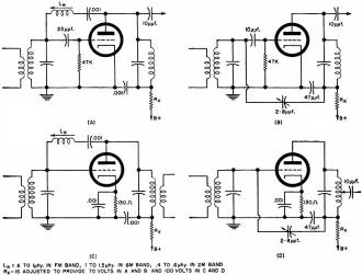
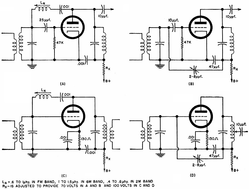
Fig. 1 - Four versions of the neutralized triode or neutrode
r.f. amplifier stage.
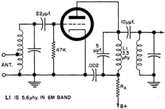
Fig. 2 - R.f. amplifier for the FM band.
The simplest circuit for the nuvistor is the neutralized triode or neutrode r.f.
amplifier. Fig. 1 shows four versions. Fig. 1A uses grid-leak bias and inductive
neutralization. Fig. 1B uses capacitive neutralization with grid-leak bias. Fig.
1C combines cathode bias with inductive neutralization while Fig. 1D uses capacitive
neutralization and cathode bias. The 6CW4 can provide gains of 25 to 50 in tuned
r.f. stages in any of these circuits. The biggest problem is keeping the amplifier
stable.
Instability Problems
Many, and perhaps most, of the instability problems can be attributed to one
rather simple cause. The tube shell needs to be well grounded. The grounding is
achieved through the socket but the socket available for these tubes presents problems
in grounding, particularly in home-brewed units. The socket was obviously designed
for installation in mass-produced equipment in which proper slots and holes are
punched and the socket is mechanically bonded to the chassis. It is difficult with
the equipment available to most amateurs and experimenters to mount this socket
as it was intended to be mounted. Even when this is managed, the grounding is not
sufficiently effective. The author has found that the best solution is to use a
thin copper plate for mounting either the socket alone or the entire r.f. stage.
A single hole is drilled for the body of the socket; the mounting ears of the socket
are turned up; the socket is slipped in the hole from the top and the mounting ears
are then soldered to the copper plate. If the nuvistor is to replace a 7- or 9-pin
miniature tube, the copper plate can be cut just large enough to replace the socket.
Even when the socket is completely grounded through a good mechanical and solder
joint to the copper, the shell of the tube may not ground perfectly because it doesn't
always make firm and low-resistance contact with the grounding lugs on the socket.
The grounding lugs can be pressed inward to narrow the gap. Also, the grounding
lugs on the nuvistor shell should be cleaned with contact cleaner and perhaps a
very fine abrasive so that a good low-resistance electrical contact is assured.
Once the nuvistor shell is well grounded, the tube presents no problems that do
not occur with any other "hot" tube.
Most experimenters are attracted by the grid-leak bias configuration because
the higher transconductance promises a better noise figure. The author has had less
trouble with cathode biasing probably because (1) the slightly lower transconductance
gives a better margin of stability and (2) cathode biasing probably provides a slight
degenerative effect. Despite this, gain and noise figures have been obtained which
are not significantly poorer. After all, a stable amplifier with slightly lower
gain is much more useful and has a better noise figure than an unstable amplifier
with higher gain.
Neutralization
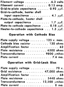
Table 1 - Characteristics of the 6CW4 tube.
Similarly, although inductive neutralization is possibly more attractive, the
author has experienced less trouble with capacitive neutralization. There are two
problems with inductive neutralization. Because of the very low grid-to-plate capacitance,
the neutralizing coil has to be rather large. But it must be positioned so that
it is not mutually coupled to the input and output coils. If there is significant
coupling, the coil will tend to increase feedback rather than neutralize it. The
compactness of the nuvistor fosters the crowding of parts and in the upper half
of the v.h.f. range, they must be crowded to keep the distributed inductances low.
It isn't easy to place the neutralizing coil in a position which both minimizes
coupling to the other coils and keeps the lead lengths short.
Much of the trouble with inductive neutralization is often traceable to a very
simple cause - the use of slug-tuned coils in which the slug is rather loose and
therefore changes position with vibration. The neutralizing slot for these tubes
is very sharp; even a slight movement of the slug can shift the parameters so that
the tube goes out of neutralization. A simple but effective solution is to slip
a cylinder of paper of appropriate thickness between the core and the inside of
the coil form so the slug fits smoothly but snugly and cannot wobble inside the
coil. A number of cases of instability have been cured in this simple manner.
Capacitive neutralization fits in nicely with an arrangement of components which
also favors isolation between input and output circuits. As in the case of larger
tubes, it is a good idea to place a shield across the nuvistor socket to isolate
the grid and plate circuits and pins. The 47-μμf. capacitor can then be a feedthrough
placed in this partitioning shield and the 2-8-μμf. neutralizing capacitor
can be supported at one end by the feedthrough terminal and at the other by a terminal
on the input coil, tuning capacitor, or a stiff wire from coil to tube grid. A miniature
variable of the MAC type, in its smallest size, is most convenient for neutralization.
However, a gimmick of twisted wires can be used although it is more trouble to adjust
for complete neutralization. Because no tuned circuit is involved, capacitive neutralization
is less critical in original adjustment and maintains complete neutralization over
a wider bandwidth.

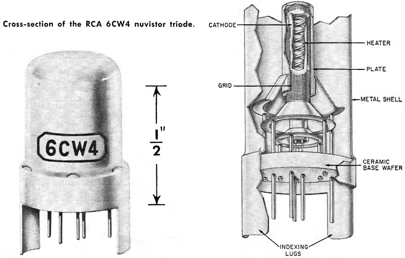
Cross-section of the RCA 6CW4 nuvistor triode.
Fig. 3 - Completely neutralized series cascode r.f. amplifier.
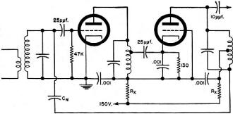
Fig. 4 - Cascaded-cascode stage is as complex as two neutrodes.
Whichever method of neutralization is used, the greatest range of stability is
achieved when the neutralization is adjusted for the low edge of the band of frequencies
to be received, or even slightly below - 45 to 50 mc., for instance, for a 6-meter
preselector or converter and 88 to 90 mc. for the FM broadcast band.
The simplest way to neutralize is to break the filament circuit, feed a strong
signal into the unit and adjust the coil or capacitor for minimum output. A slightly
better noise figure is achieved if a noise generator is available and the neutralization
is adjusted for the best noise figure. However, the difference is not significant
below the 2-meter band and adjusting for lowest feed-through provides a noise figure
well below the antenna noise.
A good enough noise figure can be achieved through the 6-meter and even the FM
broadcast band without neutralization in the circuit diagrammed in Fig. 2. Here
the plate tank, consisting of the choke and fixed capacitor, is tuned roughly to
a frequency well below the operating frequency - 50 or 60 mc. for an FM broadcast-band
tuner or 30 to 40 mc. for a 6-meter unit. This provides a low-impedance load at
the operating frequency. This low impedance, of course, reduces the gain; however,
this is partly compensated by a small amount of regeneration. Thus the gain is not
lowered too much and the noise figure is still good enough to produce an IHFM sensitivity
of 1.5 μv. or better in the FM broadcast band.
Cascode Circuits
Two nuvistors can be used in the cascode circuit. The author's attempts along
this line have not been encouraging and many of the difficulties experienced in
working with nuvistors have been due to the attempt to make them operate in cascode.
The noise figure of the series cascode is not as good as that of the neutrode unless
the plate-to-grid and plate-to-ground capacitance of the first section are both
neutralized, as diagrammed in Fig. 3. This, however, requires two neutralizing coils
and complicates the problem of placing them so that coupling to the output coil
is avoided. Also the over-all gain increases to the point where instability due
to mutual coupling is a serious problem.
Finally, nuvistors are no more immune to cross-modulation than other tubes used
in series-cascode arrangements. Indeed, the high gain increases the problem and
in any area where there are strong local signals, interference from cross-modulation
is almost inevitable. The cascaded-cascode diagrammed in Fig. 4 minimizes both the
neutralization and the cross-modulation problems, but the circuit is then as complex
as it would be with two cascaded neutrodes or pentodes.
Actually, there is little point in trying to cascode nuvistors below the 2-meter
band. A neutrode r.f. stage working into a good pentode mixer like the 6U8 or 6X8
produces a noise figure in the 3- to 4-db region through the FM band and this is
enough to provide an IHFM sensitivity of 1.5 μv. or better.
There is more point to a cascode in the 2-meter band and higher and since the
neutralizing coils can be much smaller, the problem of mutual coupling is not as
severe. However, a nuvistor neutrode first r.f. stage into a 6AK5 pentode second
r.f. stage gives as good a noise figure at 2 meters with higher gain and no more
complication in circuitry.
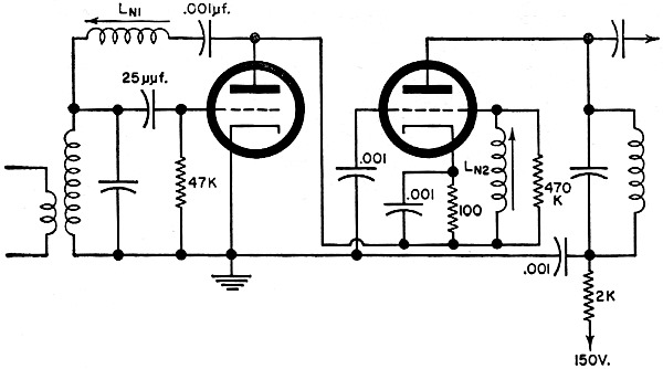
Converters & Oscillators
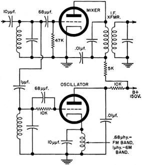
Fig. 5 - Mixer-oscillator stage that may be employed up through
the 2-meter band.
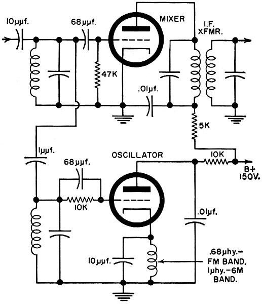
An all-nuvistor front-end or converter can be built by using three 6CW4's, one
as the r.f., another as a mixer, and the third as an oscillator. There is a tetrode
nuvistor which can be used as a mixer for higher gain and, with screen injection,
less oscillator pulling.
As a mixer the 6CW4 is connected exactly as it is when used as a grid-leak biased
amplifier, with a 47,000-ohm grid-leak resistor and a 50- to 75-μμf. grid-leak
capacitor. In the FM band and above, the length of the lead from the plate to the
first i.f. transformer may be critical. A small inductance is helpful here to reduce
input loading through the Miller effect. In the FM band, a lead length of about
one inch is right.
The 6CW4 makes an excellent oscillator in any of the circuits useful in the v.h.f.
range. The Colpitts arrangement is especially convenient. The capacitive voltage
divider is provided by the grid-to-cathode tube capacitance and the cathode-to-ground
capacitance augmented by a small capacitor across the cathode choke. The circuit
of Fig. 5 works well through the 2-meter band. The author has had no personal experience
with crystal-controlled nuvistor oscillators. It is generally agreed, however, that
they present no problems that are not common to any other suitable triode. The circuit
of Fig. 6 can be used with overtone-type crystals operating above 30 mc.
Matching & Loading
One thing that is not always taken into consideration when a nuvistor pre-amp
is placed ahead of a receiver or tuner is the impedance of the load the receiver
input will present to the nuvistor. For example, one of the most logical applications
of the nuvistor is as a preamplifier ahead of inexpensive or medium-sensitivity
FM tuners using a grounded-grid r.f. stage.
any persons have been surprised and puzzled to discover that the addition of
a nuvistor preamp in such a situation has not increased the gain appreciably. Actually,
in this instance the gain of the nuvistor cannot be expected to be much more than
2 and may well be unity. In effect, the nuvistor stage becomes the first section
of a cascode. The very low impedance of the grounded-grid amplifier loads it so
heavily that little gain is realized. The high impedance of the nuvistor should
increase the gain of the grounded-grid stage but this is not always the case since
quite often the grounded-grid stage has been designed more with an eye to reducing
radiation of the oscillator than for providing gain. Thus the resulting increase
in gain by the addition of a nuvistor may be very modest. Nevertheless, the noise
figure should be improved to some degree and this should increase the effective
sensitivity of the tuner.
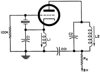
Fig. 6 - Crystal oscillator for use with overtone crystals. L1C1
is tuned to the overtone output frequency while L2C2 may be
tuned to the desired harmonic frequency.
In such a case, it is often possible to improve matters in two ways. First, a
link can be added to the nuvistor output tank so that there is a step-down to match
the low impedance of the tuner input. This will, of course, reduce the voltage fed
into the tuner. However, this should be more than made up by the increased gain
of the nuvistor itself.
In the tuner, the grounded-grid stage should be examined and, if necessary, modified
slightly to provide the highest possible input impedance. Specifically, make sure
the cathode tank is tuned to the operating frequency. When it is tuned, the impedance
will be very much higher than when it is detuned. Usually this tank will tune considerably
above the operating frequency when a preamplifier is connected in place of the antenna
because the preamp will present a much lower capacitance than the antenna transmission
line. A small trimmer can be added, if necessary, across the coil to bring it into
resonance at the operating frequency.
Even when the receiver or tuner has a grounded-cathode input stage, matching
the nuvistor preamp to the receiver input can have a significant effect on the nuvistor
gain. Assuming, as is almost always the case, that the receiver has a 300- or 72-ohm
antenna input, the nuvistor preamp should be link-coupled to the receiver or by
tapping the output off the output tank so that the low receiver input impedance
does not load the nuvistor too heavily. It may pay to try links of various turns
and coupling to obtain the best match which will be indicated by the highest gain.
Actually, with the exception of grounding, the nuvistor presents no problems
that do not occur with any "hot" tubes at the same frequencies. Indeed, once this
particular eccentricity is taken care of, it is rather less critical than any other
tube the author has used in the v.h.f. range. If the nuvistor is treated with the
same respect as to circuit layout, it is usually easier to neutralize and will remain
in neutralization over a wider frequency range. While it will not perform miracles,
it will deliver sensitivities in the v.h.f. region which were once idle dreams.
Posted May 20, 2021