|
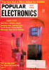
May 1963 Popular Electronics
 Table
of Contents Table
of Contents
Wax nostalgic about and learn from the history of early electronics. See articles
from
Popular Electronics,
published October 1954 - April 1985. All copyrights are hereby acknowledged.
|
For some inexplicable reason
I went backwards on this three-part Tube Family Tree series that appeared in
Popular Electronics magazine. Author Louis Garner, Jr., starts out with the early history
of vacuum tubes, beginning with Thomas Edison's incandescent light bulb and then
quickly progresses to Lee de Forest's Audion amplifier tube, and on through the
evolution of multi-grid vacuum tubes that are specially designed for low noise receiver
front ends, high power transmitters, voltage and current regulators, video cameras,
pulse forming networks, traveling wave tubes, and many other types. There is quite
a bit of information and history contained in these three installments that will
do a very nice job of introducing you to the wonder that is the electronic vacuum
tube. Here you can read
Part 1,
Part 2
and Part 3.
 A nuvistor was used in the front end of the
HP3400A True RMS Voltmeter (thanks to Michael M. for that).
Also, thanks to Bob Davis for pointing out that the Lafayette
HB-400 CB radio sported a Nuvistor in the receiver front end.
Here is a Nuvistor
info resource. See the "Nuvistors and Micro-Modules," "The Tube Family Tree,"
"Lafayette
Radio Electronics," "Hitachi
Nuvistor Ad," "Using
the Nuvistor on V.H.F. Bands," and the "The NASA 136"
articles, too. A nuvistor was used in the front end of the
HP3400A True RMS Voltmeter (thanks to Michael M. for that).
Also, thanks to Bob Davis for pointing out that the Lafayette
HB-400 CB radio sported a Nuvistor in the receiver front end.
Here is a Nuvistor
info resource. See the "Nuvistors and Micro-Modules," "The Tube Family Tree,"
"Lafayette
Radio Electronics," "Hitachi
Nuvistor Ad," "Using
the Nuvistor on V.H.F. Bands," and the "The NASA 136"
articles, too.
The Tube Family Tree, Part 1
 By Louis E. Garner, Jr. By Louis E. Garner, Jr.
Today, there are easier ways of handling electrons. Yet, the vacuum tube was,
is, and will remain one of the 20th century's greatest inventions ...
There are some who say that the electron tube has been doomed by the transistor
and its semiconductor "cousins," and that the tube, as the dinosaur, will become
extinct. To these statements, the tube, if it could speak, might well reply in the
words of the proverbial old man - I ain't dead yet. Actually, the tube is very much
alive and kicking, with new types being introduced on an almost day-to-day basis,
and handling more different kinds of jobs than ever before.
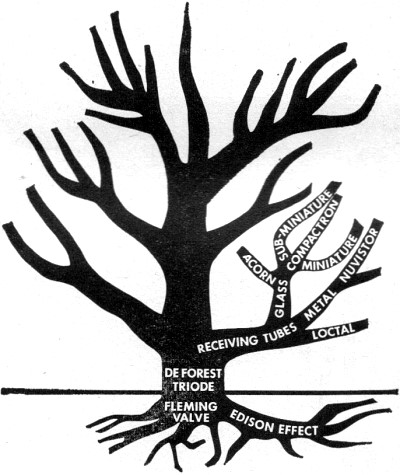
The tube "family tree" is a vigorous, strong, and healthy growing plant. Let's
examine it closely, starting with the roots and exploring the many branches and
twigs.
Birth of the Tube. The electron tube had its beginnings in distinguished
company. Thomas Alva Edison, one of the greatest inventors of all time, was experimenting
with his newly invented incandescent lamp bulbs one day when he discovered a curious
phenomenon. When he installed a small metal plate in his lamp bulb near the glowing
filament, and connected this plate through a sensitive galvanometer to the positive
filament connection, he found that a small, but easily measured, current flow took
place. Unable to explain the reason for this at the time, he nevertheless realized
that it might be potentially significant, so he obtained a patent in 1883 on what
came to be called the "Edison effect."
For many years, the Edison effect remained a classroom curiosity without any
commercial value. Edison had, however, unknowingly invented the first true electron
tube - the elementary two-electrode type we now call a diode.
 In the meantime, scientists in other fields
had started a chain of events which, eventually, would have a profound influence
on the application of the barely understood Edison effect. In 1887, Heinrich Hertz
had demonstrated that electromagnetic waves operate in accordance with the laws
governing light and heat waves, and described the basic theory upon which modern
radio communication is based. Just after the turn of the century, J. A. Fleming,
searching for an improved detector for electromagnetic waves, found that the Edison
effect could be used advantageously. It was Fleming, then, who invented the first
practical diode - the Fleming valve. The name "valve" stuck, incidentally, and,
even today, electron tubes are called "valves" in most parts of the world outside
of North America. In the meantime, scientists in other fields
had started a chain of events which, eventually, would have a profound influence
on the application of the barely understood Edison effect. In 1887, Heinrich Hertz
had demonstrated that electromagnetic waves operate in accordance with the laws
governing light and heat waves, and described the basic theory upon which modern
radio communication is based. Just after the turn of the century, J. A. Fleming,
searching for an improved detector for electromagnetic waves, found that the Edison
effect could be used advantageously. It was Fleming, then, who invented the first
practical diode - the Fleming valve. The name "valve" stuck, incidentally, and,
even today, electron tubes are called "valves" in most parts of the world outside
of North America.
The next great step forward came when Lee de Forest added a grid-like wire structure
between the filament and plate of the diode, patenting his new device, which he
dubbed the Audion, in 1906. It was de Forest who gave the electrical valve (or electron
tube, as you prefer) an entirely new capability - the ability to amplify as well
as detect weak electrical signals. He invented the triode tube, and, in so doing,
laid the basic foundation for our great radio, television, and electronics industries.
Three Basic Jobs. The electron tube's operation is relatively
simple, once the idea of electron emission is accepted. Free electrons are liberated
(or emitted) by the glowing hot filament. Since these elementary particles are negatively
charged, they are attracted to the positively charged plate, moving across the intervening
vacuum to it. This current flow is unilateral - that is, from filament to plate
and not vice versa. It is this property which permitted the early Fleming valve
to act as a detector. The filament, since it served as a source of electrons, came
to be called the cathode. Later, this term was applied generally to any electron
source in a tube (or other device), whether a filament or not.

It all started with Edison's observation that electric current
flowed back to the battery in this experimental light bulb.
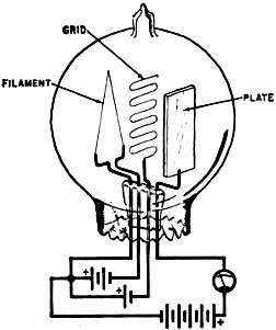
Over 20 years later, de Forest found he could control current
flow by placing a grid-like structure between plate and filament.
When de Forest added his grid-like wire between the filament and plate of the
Fleming valve, he found that a small voltage applied to this structure could influence
the plate current. Again, the operation is relatively simple. A negative voltage
applied to the grid (as it came to be called, in deference to its original appearance)
repelled the negative electrons and reduced plate current; a positive voltage applied
to the grid attracted additional electrons and accelerated them towards the plate,
increasing plate current. Since the grid, an open-like structure, intercepted few
- if any - of the electrons moving towards the plate, its power requirements were
very minute - but it could control a relatively large plate current. Thus, a small
voltage applied to the grid was able to control plate current and hence amplify
signals.
The ability to amplify made another feat possible. Once a device can be used
to amplify, a small part of the amplified signal can be fed back to the unit's input
(grid). The device then serves as its own source of signal, and this feedback can
generate alternating currents - so, it becomes an oscillator.
With the addition of the grid, the electron tube became capable of performing
the three basic jobs it has handled from the first decade of this century to the
present day: detection, amplification, and oscillation.
 The Tube's Evolution. Fleming's valve
was a two-element tube, or diode, and consisted of a filamentary cathode and a plate.
If, as was discovered, the filament is operated on 60-cycle a.c. line power instead
of d.c., a certain amount of the line "hum" will appear in the plate circuit. This
led to the addition of a separate cathode ... essentially a metal tube coated with
chemical elements which emit electrons when heated. The Tube's Evolution. Fleming's valve
was a two-element tube, or diode, and consisted of a filamentary cathode and a plate.
If, as was discovered, the filament is operated on 60-cycle a.c. line power instead
of d.c., a certain amount of the line "hum" will appear in the plate circuit. This
led to the addition of a separate cathode ... essentially a metal tube coated with
chemical elements which emit electrons when heated.
The tube is still a diode, however, with the indirectly heated cathode and the
plate serving as its principle elements. The filament is reduced to the simple role
of heating the cathode and, quite appropriately, is often called a heater.
 When de Forest added a control grid, the tube
became a three-element device, or triode. In practice, the triode was found to suffer
from a serious disadvantage when used as a tuned r.f. amplifier. There is a fair
amount of electrical capacity between the grid and plate. This permitted a percentage
of the signal in the plate circuit to be coupled back to the grid, setting up the
basic condition for oscillation. When de Forest added a control grid, the tube
became a three-element device, or triode. In practice, the triode was found to suffer
from a serious disadvantage when used as a tuned r.f. amplifier. There is a fair
amount of electrical capacity between the grid and plate. This permitted a percentage
of the signal in the plate circuit to be coupled back to the grid, setting up the
basic condition for oscillation.
Thus, early r.f. amplifiers tended to be quite unstable, and a variety of schemes
were developed to neutralize the effects of grid/plate capacitance. In general,
these consisted of introducing enough inverse (or negative) feedback from the plate
tuned circuit into the grid circuit to counteract the direct feedback inside the
tube and prevent unwanted oscillation.
The next forward step came with the introduction of a second grid to serve as
a shield or screen between the (control) grid and plate. By reducing grid/plate
capacity, the four-element tube, or tetrode, permitted r.f. amplifiers to be assembled
without special neutralization circuits.
It was soon discovered, however, that the tetrode, as the triode before it, had
a peculiar disadvantage of its own. For effective shielding, the screen grid was
given a positive charge. This accelerated the electrons tremendously in their trip
to the plate, causing the electrons to strike the plate with sufficient force to
"knock" other electrons off the plate material. In a sense, the plate became an
electron emitter, secondary to the cathode.
With the proper combination of plate and screen voltages, more electrons would
be emitted by the plate than were received by it, and these, traveling back to the
positive-charged screen grid, caused a curious phenomenon. Under certain conditions,
an increase in plate voltage would cause a decrease in plate current . . . as if
the tube acted like a negative resistance. Again, the net result was instability
and the tendency to oscillate when the tetrode was used as an amplifier.
 In an effort to reduce, or "suppress," the plate's
secondary emission, a third grid was added between the screen grid and plate and
connected back to the tube's cathode, creating the five-element or pentode tube.
This third grid was called, appropriately, the suppressor grid. It served to repel
the secondary electrons back to the plate without appreciably affecting the normal
cathode-to-plate electron flow. Today, the pentode is perhaps the most widely used
basic tube type. In an effort to reduce, or "suppress," the plate's
secondary emission, a third grid was added between the screen grid and plate and
connected back to the tube's cathode, creating the five-element or pentode tube.
This third grid was called, appropriately, the suppressor grid. It served to repel
the secondary electrons back to the plate without appreciably affecting the normal
cathode-to-plate electron flow. Today, the pentode is perhaps the most widely used
basic tube type.
Somewhat later, it was found that a single cathode could be used for more than
one function if additional electrodes were added outside the normal control range
of the grid elements. This, in turn, led to the development of multi-purpose tubes.
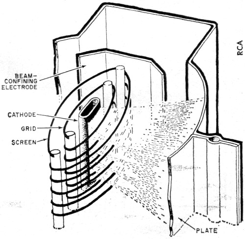
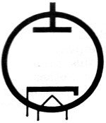
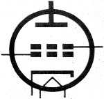
To make greater use of the stream of electrons moving from cathode
to plate, this system of beam confining was developed. Practical all modern power
amplifier types use these beam-forming plates.
Beam Power Tube. The basic screen grid, whether in a tetrode
or pentode, requires a fair amount of power for operation-power which does not,
however, contribute to the strength of the amplified signal. Where very small amounts
of power are handled, as in weak-signal amplifiers, the power loss is small and
relatively unimportant. If a large amount of power is handled, as in tubes designed
to handle several watts, then the power loss becomes significant, contributing to
a loss in operating efficiency.
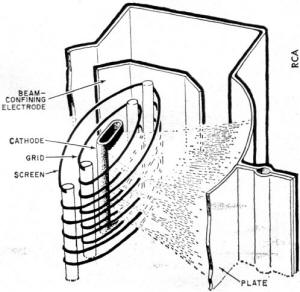
This led to the development of the beam power tube in which the control and screen
grid wires were aligned in the same plane, so that the resulting flow of electrons
was formed in parallel sheets or "beams" between the cathode and plate. Beam-confining
electrodes were added to shape the resulting beams and confine the electron flow
between the grid wires, thus preventing electron movement to the support leads on
which the grids were wound.
The resulting tube had much smaller screen currents than earlier tetrodes (and
pentodes) with comparable power-handling ability, and thus was more efficient. At
the same time, it was found that the beam power tube had much greater power sensitivity
than earlier types. Today, beam power tubes are used extensively at both r.f. and
audio frequencies where more than a few watts are involved.
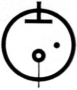
Gas-Filled Tubes. The majority of electron tubes are designed
to operate within a vacuum, so that there will be no gas molecules present to interfere
with the free movement of electrons between the cathode and plate electrodes. In
fact, during the manufacturing process, a metallic substance is evaporated within
the tube, forming a film on its walls and absorbing the last traces of gas: this
element is called the getter.
For some applications, however, limited amounts of specific gases may be introduced
in a tube. Where a gas is present, the gas atoms can, under certain conditions,
ionize; the gas atoms are partially stripped of their outer electrons and become
positively charged ions. The gas ions move towards the cathode while the free electrons
move towards the plate.
 Gas may be ionized by the application of heat
and moderate voltages or by the application of relatively high voltages. This latter
fact has led to the development of several types of cold-cathode tubes - tubes which
do not require a filament or heater - the simplest examples of which are diode rectifiers
such as the OZ4, voltage regulator tubes, and neon lamps. Gas may be ionized by the application of heat
and moderate voltages or by the application of relatively high voltages. This latter
fact has led to the development of several types of cold-cathode tubes - tubes which
do not require a filament or heater - the simplest examples of which are diode rectifiers
such as the OZ4, voltage regulator tubes, and neon lamps.
The presence of gas within a tube has several primary effects. First, of course,
positively charged gas ions tend to reduce the tube's effective plate-to-cathode
resistance, thus reducing its internal voltage drop. For this reason, gas-filled
(generally, mercury-vapor) rectifiers are extremely popular where large currents
are handled. Second, an ionized gas gives the tube an "all or nothing" characteristic.
Until ionization occurs, relatively little current can flow. Once the gas is ionized,
however, current reaches a maximum very quickly, and stays at that maximum value
(determined by load resistances and supply voltages) until the plate voltage is
reduced to a very low value or cut off altogether.
Gas-filled triodes, or thyratrons, like gas-filled diodes, have an "all-or-nothing"
characteristic, but with one difference. The difference is that the control grid
in the thyratron, being relatively close to the cathode compared to the plate, can
be used to "trigger" ionization even though the plate voltage is below the value
normally required to ionize the gas. Thus, a small signal (or trigger) voltage applied
to the grid can switch the tube from a non-conducting state very quickly. Thyratrons
are used extensively as relaxation oscillators and for control and switching applications.
A number of gas-filled cold-cathode triodes have been manufactured for special
applications. Their operation is somewhat similar to that of the conventional thyratron,
except that no filament is used. The most familiar example of this type of tube
is the flash tube used in photographic electronic flash lamps.
Receiving Tubes. By far the most popular general class of tubes
are low- to medium-power types primarily designed for use in radio and television
receivers. This general class encompasses all the basic tube types-diodes, triodes,
tetrodes, pentodes, beam power, and multi-purpose tubes.
In the early days, there was little need to identify tubes except by their manufacturer's
name, for most units were essentially the same. Later, as more types were developed,
identifying type numbers were introduced. These served to identify a particular
type of tube in terms of its characteristics, permitting tubes produced by different
firms but having the same type number to be used interchangeably. The first type
numbers were simple numerical designations, such as 01A, 15, 19, 20, 42, 45, 76,
and 80.
As more and more types were developed, a different numbering system became necessary.
The tube manufacturers decided to adopt a system of numbers and letters such that
the type number itself would give an indication of the tube's basic application.
With this system, the first number would indicate the tube's nominal filament voltage,
a middle letter the intended application (amplifier or rectifier, for example),
and the last number the number of active elements. Amplifier type tubes were to
receive letter designations from the first part of the alphabet, rectifiers from
the end of the alphabet.
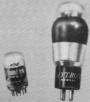
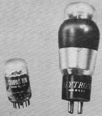
Multiple triode sections in one glass envelope are not as new
as you might think. The 6A3 tube of the 1930's (right) had two triode sections,
but they were wired together. The current compactron (left) has three triodes in
its envelope, and each grid, plate, and cathode goes to a separate base pin.

Gone but not forgotten are these three pioneers. The 200A (left)
was one of the first mass-produced tubes. A 954 Acorn helped introduce VHF to communication
services. At right is an 1851, a super-high-gain tube developed just before World
War II.

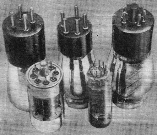
As the internal structure of vacuum tubes became
more complex, the necessity arose to provide pin connections. Here are some examples
of the changing styles from 1925 to 1963. Along the back row (left to right); 4-pin
and 5-pin tubes, circa 1925-1935; and the octal, 1935-19-. In the front row: the
loctal (left). and the popular 9-pin miniature tube.
How Numbering System Worked. A type 6A3 was a tube with a nominal
6-volt filament (actually 6.3 volts), an amplifier type (A), with three active elements
- filamentary cathode, grid, and plate. The 2A3 was a similar type, but with a 2-volt
(actually 2.5-volt) filament. Similarly, the 6D6 was a tube with a 6-volt filament,
an amplifier (D) type, with six active elements - filament, cathode, control grid,
screen grid, suppressor grid, and plate. A 5Y3 was a tube with a 5-volt filament,
rectifier type (Y), with three elements - filamentary cathode and two plates; the
5Z4 was similar, but with an extra element - an indirectly heated cathode.
Unfortunately, even this seemingly ideal system was inadequate, for the introduction
of new types soon outran available type numbers. Today, type number designations
still use number-letter combinations, and the first number generally (not always)
indicates nominal filament voltage, but the remaining part of the type number does
not always hold to its original meaning.
Tube Envelopes. Tube construction techniques, too, have undergone
many changes as the "family tree" has grown. Originally, tubes were assembled in
glass envelopes almost identical to those used for incandescent lamp bulbs. Later,
refined designs were introduced with connection pins which allowed tubes to be plugged
into their sockets (rather than screwed in, as with lamp bulbs).
Metal envelopes became popular because they carried the advantages of built-in
shielding and were less prone to breakage than glass types. Special shapes were
designed for high-frequency tubes to reduce electrode leads to minimum length ...
such as the now-famous Acorn tube. Still later, miniature 7- and 9-pin glass types
were developed.
Today, the miniature glass tube is the most popular, general type, although several
new types of construction have been introduced in recent years.
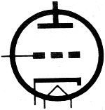
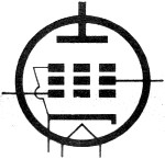
Pentagrid Converter. As radio receiver circuits became more
and more complex, multi-purpose tube designs became increasingly popular. The use
of these permitted more compact receiver chassis layouts without, at the same time,
compromising circuit sophistication. Some of these multi-purpose units were (and
are) simply the elements of two or more tubes combined in a single envelope, but
some special types were developed, the most popular of which is the pentagrid converter.
 The pentagrid converter has, as the name implies,
five grid structures. Its primary application is in superheterodyne receivers, where
it is used as a combination local oscillator and mixer. The pentagrid converter has, as the name implies,
five grid structures. Its primary application is in superheterodyne receivers, where
it is used as a combination local oscillator and mixer.
In operation, the cathode, control grid, and screen grid are used as the essential
elements of a "triode" tube with appropriate components to form an oscillator. The
incoming r.f. signal is applied to the second control grid (grid 2), which is shielded
by the two-element screen grid. The cathode-to-plate electron stream is common to
both control grids, hence the locally generated signal and incoming r.f. signal
are combined in the stream and electrically "mixed" by the time the stream reaches
the plate.
The Compactron. Developed primarily for TV applications and
representing the present-day "ultimate" in multi-purpose tubes, the compactron is
a squat, 12-pin tube with a glass envelope similar to that employed with 7- and
9-pin miniatures (but broader) and may combine the functions of as many as three
or four different tubes in a single unit.
Ceramic Tubes. An ultra-miniature type designed for high-frequency
applications, ceramic tubes are made up "sandwich-fashion" with alternate metal
electrodes and ceramic spacer-insulators. They are used primarily in VHF and UHF
receiver designs, in radar equipment, and in similar applications, although a few
types have been designed for TV receiver and FM set work.
The Nuvistor. Just as the compactron represents the present-day
ultimate in multi-purpose tube construction, the nuvistor is the latest version
of the metal envelope tube popular a few years ago. Nuvistors are manufactured in
the basic generic types (triodes, tetrodes, etc.) and are extremely small physically
... not appreciably larger, in fact, than the typical transistor and actually smaller
than some power transistor types. They are especially well suited to compact receiver
design and are used extensively in TV, FM, and VHF receivers.
Part 2 of this article will explore the transmitting tube "branch" of the tube
"family tree," as well as the development of various types of phototubes and cathode-ray
tubes.
Posted November 30, 2021
(updated from original post on 4/30/2014)
|