|
July 1965 Electronics World
 Table of Contents
Wax nostalgic about and learn from the history of early electronics. See articles
from
Electronics World, published May 1959
- December 1971. All copyrights hereby acknowledged.
|
The
VOR (very
high frequency omnidirectional range) electronic aircraft navigation concept is
one of the most ingenious, elegant system solutions ever designed. Using what is
essentially a very simple phase comparison method, a navigation signal is
generated that is precise and reliable enough to be trusted for instrument
flight rules (IFR)
by military, commercial, and private aviation. A physically rotating antenna in
the ground station was originally used, but eventually an electronically swept
method replaced it so there are no moving parts. I was trained on VOR navigation
during private pilot flight training in the early 1980's, before there was a
GPS. GPS has largely replaced VOR (and VORTAC) as a primary navigation tool, but
a lot of airplanes still carry VOR equipment either as a backup or simply
because the pilot prefers that method. IFR can be flown without VOR/VORTAC or
GPS under certain conditions, but no sane pilot would try it without at least one
of the two.
Part 1:
Low-Frequency
Ranges & Direction Finding, Part 2:
V.H.F.
Omnidirectional Range (VOR), Part 3:
Terminal
Instrument Navigation (ILS & GCA)
Radio Aids to Aircraft Navigation - Part 2: V.H.F. Omnidirectional
Range (VOR)
 By
Francis A. Gicca By
Francis A. Gicca
Senior Engineer, Raytheon Co.
Description and use of the most flexible, accurate, and simple widely used navigation
system for planes.
Last month we discussed the two low-frequency systems of long-range navigation.
The low-frequency radio ranges and direction finding are capable of guiding an airplane
along the civil airways, but not without some serious disadvantages and limitations.
Radio ranges are limited by their inability to provide more than four navigational
courses. Direction finders and the radio ranges both suffer from the poor propagation
characteristics of low frequencies which causes navigation errors due to static
and atmospheric bending of the beams.
The radio-range and direction-finding systems of aircraft navigation were developed
at a time when low frequencies were the only frequencies practical for broadcasting.
As time passed and higher frequencies became usable it was obvious that v.h.f. transmissions
for navigation would be highly desirable since v.h.f. is relatively static-free
and not susceptible to bending as lower frequencies are. Engineers could have developed
a v.h.f. radio-range system similar to the low-frequency ranges, but they realized
that the four-course limitation was a serious one. They felt that whatever system
they developed for v.h.f. navigation should be similar to ADF and include 360 radio
courses, a course for every degree on the compass.
The result was VOR, short for V.h.f. Omnidirectional Range, sometimes also known
as "Omni." Without a doubt, VOR is the most flexible, accurate, and simple widely
used navigation system. The receiver is relatively simple and inexpensive and is
generally a part of v.h.f. communications equipment.
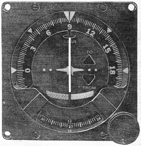
VOR
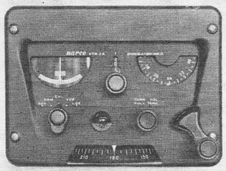
VOR receiver. "Left-Right" meter with "To-From" indication, is
at left. The course-selector dial is at the bottom.
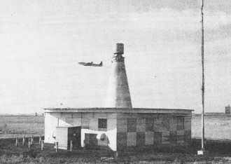
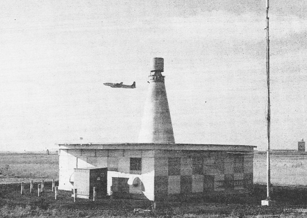
VOR and TACAN transmitter site. The main VOR antenna array is
housed in the base of the cone on top of the building. It is a four-loop antenna
assembly. The cylinder on top of the cone is the antenna for the Air Force-developed
TACAN navigation system. The vertical antenna on the pole to the right of the main
building is a distance-measuring equipment (DME) antenna. DME is currently being
discontinued.
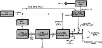
Fig. 5 - Basic block diagram of the v.h.f. omnidirectional range
(VOR) transmitter.
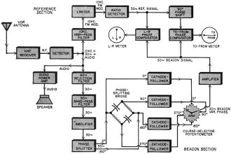
Fig. 6 - Complete block diagram of the VOR receiver discussed
in the text.
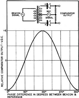
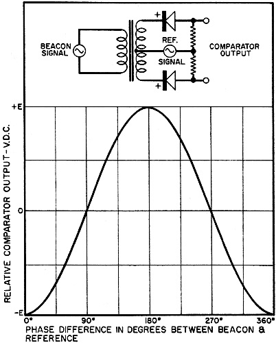
Fig. 7 - Phase comparator characteristics.
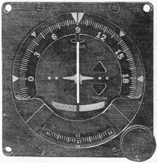
Single-unit VOR indicator/course selector.
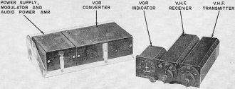
VOR receiving and communications system. Indicator, receiver
and transmitter are installed on the cockpit flight panel.
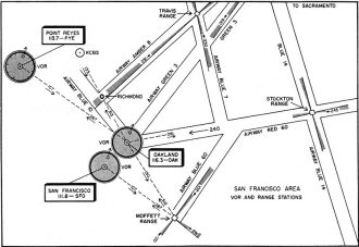
Fig. 8 - Simplified navigational chart showing VOR stations and
low-frequency ranges.
In order to understand the operation of the VOR system, it is first necessary
to understand the operation of a VOR transmitter. In essence, the operation of a
VOR transmitter can be likened to that of a light beacon rotating at a uniform rate.
If the beacon revolves at 1 rpm and if a fixed red light atop the beacon is flashed
as the beam points North, an observer with a stopwatch can determine his bearing
from the beacon merely by starting the watch when the red light flashes and stopping
it when the beacon's beam flashes past him. The azimuth angle measured from North
is then directly proportional to the elapsed time measured by the stopwatch.
A VOR transmitter functions in a manner similar to the rotating beacon and flashing
red light. In the VOR transmitter, the rotating beacon is replaced by a signal whose
phase rotates from zero to 360 degrees as the signal is beamed and rotated clockwise
in a narrow beam from magnetic North. When the electronic beam points North the
phase is at zero degrees, as the electronic beam passes East the phase is at 90
degrees, and so on for all points of the compass. Every degree of the compass corresponds
to an equal amount of phase shift in the beacon signal.
The reference flashing red light is electronically replaced by a reference signal
whose phase remains at zero degrees irrespective of direction. In order for a pilot
to determine his azimuthal angle from the transmitter it is only necessary to measure
the phase shift of the beacon signal in comparison to the phase of the reference
signal. The number of degrees of phase shift measured corresponds exactly to the
number of azimuthal degrees from North referred to the transmitting station employed.
For example, if an airplane is located due North from the station, it will receive
the beacon and reference signals in-phase. If the pilot somehow measures the phase
difference between these two signals he will find it to be zero degrees. The pilot
then knows he must be on a line at zero degrees, or due North, from the station.
If the airplane is located due South from the station it receives the beacon and
reference signals out-of-phase. If the pilot again measures the phase difference
he finds it to be 180 degrees. The pilot knows he must now be on a radial at 180
degrees, or due South, from the station. In a similar manner, a pilot can determine
his position along any radial from the station.
The purpose of a VOR transmitter is to broadcast the beacon and reference signals
as well as voice communications. A complex antenna array transmits this information
in the v.h.f. band of 108 to 118 megacycles. The v.h.f. carrier is first amplitude-modulated
at 30 per-cent with a 10 kc. (actually 9960-cycle) signal. In turn, this 10 kc.
signal is frequency-modulated with a 30-cycle reference signal with a maximum deviation
of ±480 cycles above and below 10 kc. This 30-cycle signal which has been
coded onto the 10 kc, subcarrier forms the reference signal of the VOR system and
remains fixed in phase.
The beacon signal could be created by transmitting the unmodulated v.h.f. carrier
from a highly directional antenna and then rotating this antenna 30 times each second.
This would, in essence, amplitude-modulate the v.h.f. carrier at a 30-cycle rate
whose relative phase varies as a function of antenna position. When the antenna
points directly at an observer, the v.h.f. signal which he receives has maximum
strength. However, when the antenna is pointed directly away from the observer,
the signal is received with minimum strength. The amplitude of this received signal,
then, varies as the antenna rotates and the signal detected by the receiver is identical
to one amplitude-modulated at a 30-cycle rate. Note, however, that the amplitude
maximum always occurs when the antenna is pointed directly at the receiver, irrespective
of the receiver's azimuthal position from the transmitter. The result is that the
phase of the amplitude modulation with respect to a fixed phase reference signal
varies with azimuth around the station.
It is apparent that it would be extremely difficult to physically rotate a heavy
antenna 30 times each second, which corresponds to 1800 rpm, The solution to this
problem is shown in Fig. 5, which shows a simplified block diagram of a VOR transmitter.
A complex antenna array is used to create the rotating v.h.f. radiation pattern.
This antenna array consists of a series of directional antennas spaced evenly around
the transmitter site. These antennas are connected to a rotating goniometer which,
in turn, is connected to the v.h.f. transmitter output. The goniometer is essentially
a capacitative switch which successively switches v.h.f. carrier energy from antenna
to antenna. This goniometer is rotated at 1800 rpm by a synchronous motor in order
to effectively rotate the beacon signal at a 30-cycle rate whose phase varies as
a function of azimuth. A central non-directional antenna transmits the 10 kc. frequency-modulated
reference signal and voice modulations.
VOR Reception
Fig. 6 is the block diagram of National Aeronautical Company's "Mark II," a popular,
low-priced VOR receiver. The r.f. section of the "Mark II" is a fairly conventional
v.h.f. superheterodyne receiver plus v.h.f. transmitter for communications. The
VOR converter section begins at the detected audio output of the receiver. Remember
that the reference 30-cycle signal is coded as frequency-modulation on a 10 kc.
sub-carrier which, in turn, is amplitude-modulated on the main v.h.f. carrier. Since
the audio detector of the v.h.f. receiver detects all amplitude modulation present
on the carrier, the 10 kc. sub-carrier is detected by the receiver and appears as
a 10 kc. audio signal. In order to recover the 30-cycle reference signal which is
frequency-modulated on this sub carrier, it is first necessary to separate the 10
kc. sub carrier from other audio frequencies present in the audio output of the
receiver. A 10 kc. high-pass filter achieves this separation. The clean 10 kc. signal
is then amplified and limited in amplitude to remove all stray amplitude modulation
present. The limited signal is then applied to a ratio detector which frequency
detects the 30-cycle reference signal from the 10 kc. carrier. In this manner, the
fixed-phase reference is extracted.
The 30-cycle variable-phase beacon signal is already present at the audio output
of the receiver since it was simply amplitude-modulated on the v.h.f. carrier. The
variable-phase, or beacon, channel of the "Mark II" consists first of a 60-cycle
rejection filter. The purpose of this filter is to remove 60-cycle components present
in the audio output which are generated by single-blade propellers rotating at approximately
1800 rpm. Unless removed, this 60-cycle spurious signal can cause errors in the
final readings and cause slow oscillations of the meter needles. Following the rejection
filter, a 30-cycle bandpass filter removes voice frequencies and the 10 kc. reference
sub carrier from the beacon channel. After amplification and further filtering,
the beacon signal is applied to a phase-splitter which generates two equal voltages
180 degrees out-of-phase. These push-pull voltages then drive a phase-splitting
bridge which produces four output voltages, each delayed an additional 90 degrees
in phase than the previous voltage. This circuit consists of two resistors and capacitors
connected in a bridge and arranged so that each corner of the bridge has equal beacon
signal voltages, but at exactly 90-degree intervals of phase. These four voltages
are connected to four cathode-followers in order to obtain four low-impedance beacon
signal sources.
Since azimuthal position will be determined by measuring the phase of the beacon
signal in comparison to the reference signal, the remainder of the circuits are
designed to measure this phase difference. In the "Mark II," the four cathode-followers
feed a symmetrically tapped potentiometer known as the "Course Selector." Since
each tap of this potentiometer is connected to the four beacon signals which are
each 90 degrees out-of-phase, the course selector functions as a continuously variable
phase shifter. The output of the course selector is the beacon signal whose phase
can be continuously varied through 360 degrees depending upon the position of the
potentiometer arm.
Following amplification of the 30-cycle beacon signal, it is applied to two phase
comparators. Each of these comparators consists of two diodes which are switched
on and off by the 30-cycle reference signal. When conducting, these diodes allow
the beacon signal to pass through. When non-conducting, the diodes reject the beacon
signal. Since this action occurs in synchronism with the reference signal, which
is also at 30 cycles, the phase comparator performs as a rectifier of the beacon
signal. However, the magnitude and polarity of the rectified d.c. voltage thus produced
is a function of the phase difference between beacon and reference signals. If the
two signals are exactly 90 or 270 degrees out-of-phase, no d.c. voltage is produced.
If the phase shift is between 91 and 269 degrees, a positive d.c. voltage is produced
which reaches maximum amplitude at 180 degrees. If the phase shift is between 89
and 271 degrees, a negative d.c. voltage is produced which reaches maximum amplitude
at 0 degrees. Fig. 7 shows the d.c. produced by a phase comparator as a function
of phase difference between the two voltages.
Consider the "Left-Right" phase comparator of Fig. 6. This is driven by beacon
and reference signals. When a VOR signal is received, an azimuthal phase difference
will exist between beacon and reference signals which produces a d.c. voltage proportional
to this phase difference from the phase comparator. This d.c. voltage is applied
to a "Left-Right" meter which is deflected by this voltage. If the course selector
dial is rotated, the phase of the beacon signal can be adjusted until it is 90 degrees
out-of-phase with the reference signal. At this point, the out-put of the phase
comparator is zero and the "Left-Right" meter centers.
If the course selector dial is calibrated in degrees of phase shift introduced,
then the course-selector dial indicates directly the azimuth radial along which
the aircraft is located. Unfortunately, the reading is ambiguous since the "Left-Right"
meter will center at a phase shift of 270 degrees, as well as 90 degrees (refer
to Fig. 7). The purpose of the "To-From" phase comparator and meter is to resolve
this ambiguity.
Note that the reference signal that is used for the "To-From" phase comparator
is shifted in phase so as to lag by 90 degrees the reference of the "Left-Right"
comparator. Assume that the beacon signal has been adjusted to lag the standard
reference signal by 90 degrees thereby centering the "Left-Right" meter. Since the
"To-From" reference lags the standard reference by 90 degrees, the "To-From" comparator
sees two signals which are exactly in-phase. This produces maximum negative d.c.
voltage and deflects the "To-From" meter fully into the "To" region. If the beacon
signal has been phase shifted 270 degrees rather than 90 degrees, again centering
the "Left-Right" meter, the "To-From" comparator now sees that the two signals are
exactly 180 degrees out-of-phase. This produces maximum positive d.c. voltage which
fully deflects the "To-From" meter into the "From" region. In this manner, the "To-From"
meter indicates which of the two possible "Left-Right" zero meter readings has been
selected.
VOR receivers have been designed so that when the "Left-Right" meter is centered
and the "To-From" meter reads "To," the course selector indicates the magnetic heading
that will lead the aircraft towards the VOR station. Conversely, a "From" reading
indicates the heading which will lead the aircraft away from the VOR station. In
following a course to a VOR station, the "Left-Right" meter is arranged so that
it will deflect in a direction that indicates which direction to fly in order to
stay on course. Assume that a VOR station is to be approached along an 80-degree
radial. The VOR receiver is tuned to the station and the course selector dial set
at 80 degrees. The "Left-Right" meter will center and the "To-From" meter indicate
"To" when the plane is on course. If the "Left-Right" meter reading drifts off center
towards the left, this indicates that the pilot must execute a turn to the left
in order to stay on course. In this manner, a pilot can easily remain on course
by merely keeping the "Left-Right" needle centered. If the pilot is approaching
the VOR station on an 80-degree radial as just described, as the flight goes on
the "To-From" needle will flicker and finally swing to "From." At this point, the
station has been passed and the airplane is now heading away from the VOR station.
The operation of the "Mark II" just described helps indicate the great versatility
of the VOR system of navigation. In contrast to its closest relative, ADF, any radial
can be flown and is indicated directly in degrees on the course-selector dial. ADF
cannot achieve this without resort to a magnetic compass for proper heading. Furthermore,
the "Left-Right" meter indicates directly the plane's deviation off its planned
course. As can be seen in the photo (page 55), the "Mark II" VOR receiver is small
and compact. The course selector dial is horizontal and at the bottom of the receiver.
The "To-From" meter is arranged to show either the word "To" or "From" at the center
of the "Left-Right" meter.
The Lear "Navcom 100" VOR navigating system is unique in its presentation of
navigation information. A single 3-inch-square meter contains the course selector
dial, "Left-Right" meter, and "To-From" indicator. The course-selector variable
phase shifter uses a servo resolver rather than a tapped potentiometer. A rotating
coil in the resolver picks off the proper phase beacon signal from two fixed coils
electrically 90 degrees out-of-phase. A resolver is more accurate as a phase shifter
than a tapped potentiometer, but it is more expensive. Since the "Mark II" was designed
for absolute minimum cost, it uses the tapped-potentiometer type of phase shifter.
VOR is accurate. The maximum angular error permitted by the Federal Aviation
Agency is plus or minus four degrees. Most VOR receivers are far more accurate than
this, generally better than two degrees. Ironically, the principal weakness of VOR
is due to its very use of v.h.f. frequencies. Although v.h.f. is static free, it
propagates by "line of sight." That is, if the transmitter can be seen from the
aircraft, the VOR signal can be received. Unfortunately, this means that there can
be no obstructions between the transmitter and navigating aircraft to deflect the
VOR signals. In turn, this requires that the aircraft fly at an altitude sufficient
to guarantee that no mountains or other obstructions intervene. Therefore, VOR is
practically useless below about two thousand feet. Since most air navigation is
conducted well above two thousand feet, this restriction is not serious except when
an airplane must fly low, as it must when preparing to land. All things taken into
account, VOR presents less drawbacks than any other system in use and remains the
backbone of U.S. long-range navigation.
Navigating with VOR
Fig. 8 shows a simplified radio navigation chart for the San Francisco area similar
to that of Fig. 4, Part 1, but including VOR stations. Three VOR transmitters are
shown: Point Reyes VOR (identified by the letters "PYE" on 113.7 mc.), Oakland VOR
(OAK on 116.3 mc.), and San Francisco VOR (SFO on 111.8 mc.). Generally, VOR stations
are located on the civil airways to allow VOR flight along the airways. Many stations
are also strategically located off the airways in order to facilitate short range
point-to-point travel and allow the taking of running fixes on the airways.
Suppose an airplane wishes to fly from the east along airway RED 60 to Oakland
VOR. A magnetic heading of 240 degrees towards Oakland VOR from the east will place
an airplane along the center radial of airway RED 60. The pilot tunes his VOR receiver
to Oakland VOR at 116.3 mc. and sets the course selector dial to 240 degrees. When
the "Left-Right" meter is centered and the "To-From" indicator shows "To," the pilot
knows he is on the center of airway RED 60. However, this will be true irrespective
of the aircraft's heading since VOR relays position along a radial from the station
and does not indicate heading. Of course, if the plane's heading is away from the
radial, the "Left-Right" needle will deflect as the plane leaves the radial. However,
it is unnecessary for the aircraft to head aimlessly in the wrong direction since
the course selector indicates the magnetic heading which corresponds to the VOR
radial.
Thus the pilot will begin approaching Oakland VOR by flying a magnetic compass
heading of 240 degrees. After a while, though, the "Left-Right" needle will begin
to deflect to one side or the other. Why does the needle deflect if the proper magnetic
heading was chosen? The most common cause is wind which is drifting the plane off
the radial. When the pilot re-adjusts his heading to center the needle he is heading
his airplane into the wind to correct for drift. Thus, VOR corrects for the pilot's
biggest navigational problem, wind drift. ADF does not correct for drift since ADF
cannot determine along which radial the aircraft is flying as VOR can. An aircraft
approaching a station with ADF will fly a wide curve to the station as wind pushes
the plane off course.
As with low-frequency navigation aids, navigation can be made considerably easier
if several types of equipment are used simultaneously. Flying from Travis Range
to Oakland VOR via airways AMBER 8 and BLUE 10 can be easily accomplished by an
aircraft equipped with a VOR receiver and a radio-range or ADF receiver. The pilot
can either home on Richmond beacon with his ADF or use the on-course signal from
Travis Range to place him on airway AMBER 8.
The inbound radial to Oakland VOR along airway BLUE 10 corresponds to a magnetic
heading of 133 degrees. Therefore, the pilot tunes his receiver to Oakland VOR and
sets the course selector to 133 degrees, the final radial he wishes to fly on BLUE
10. As the aircraft flies along AMBER 8, the "Left-Right" meter will point to the
right indicating that the 133 degree radial is farther to the South, and the "To-From"
indicator will indicate "To." As the junction of the two airways is approached the
"Left-Right" needle will start centering until it finally centers at the junction.
At this point the pilot turns his plane inbound to a magnetic heading of 133 degrees
and follows the VOR signal to Oakland VOR.
As can be seen, ADF and the radio ranges are good navigational aids in themselves,
but when used with VOR they help make long-range navigation simplicity itself. Today
most fliers rely on VOR as their primary navigational aid and supplement VOR with
ADF and the ranges to provide fixes along the course which allows exact determination
of position along this course.
Unfortunately, long-range navigation is only one of a pilot's many navigational
problems. VOR, ADF, and the radio ranges will lead a pilot to his final destination,
but they won't get the air-plane on the ground. How does a pilot land his airplane
when the visibility is less than two miles which is less than twice the length of
many runways?
Next month we shall conclude this series by examining the various electronic
systems designed to allow an aircraft to perform a safe instrument landing. (Concluded
next month)
Posted January 16, 2023
|