|
July 1960 Electronics World
 Table of Contents
Wax nostalgic about and learn from the history of early electronics. See articles
from
Electronics World, published May 1959
- December 1971. All copyrights hereby acknowledged.
|
From the time the
Wright brothers made
their historic 1903 flight at Kill Devil Hills on the coast of North Carolina, aviation
progressed at a geometric rate. For safety, convenience, and commercial reasons,
navigation methods and equipment necessarily developed alongside aircraft advances.
Both realms required a huge amount of innovation, research, and development. All
first-world countries participated in the effort in order to establish and/or maintain
leadership in particular realms of the science. One of the earliest navigational
aids was the creation of detailed maps with easily recognized landmarks, and placement
of flags and windsocks where they would be easily visible from an airborne vantage
point. That facilitated more accurate "dead reckoning" navigation.
Bonfires were built in specific locations for the benefit of night flyers. Next
came electronic navigational equipment like direction finding (zeroing in on a commercial
radio broadcast tower), omnidirectional (VOR and VORTAC)
broadcast for flying bearing relative to fixed stations broadcasting compass information,
and sites designed for long range navigation (LORAN). VOR was a particularly ingenuous
concept that was a game changer, allowing precision navigation even in zero visibility
conditions. Of course now there is
GPS, which
makes all previous systems like prehistoric.
Part 1:
Low-Frequency
Ranges & Direction Finding, Part 2:
V.H.F.
Omnidirectional Range (VOR), Part 3:
Terminal
Instrument Navigation (ILS & GCA)
Radio Aids to Aircraft Navigation - Part 1: Low-Frequency Ranges &
Direction Finding
 By Francis A. Gicca, Senior Engineer. Raytheon
Co. By Francis A. Gicca, Senior Engineer. Raytheon
Co.
Operation and use of important electronic aids that make flying safe - with emphasis
on private-plane applications.
Our author is well-qualified to write on this important subject. His professional
work is directly concerned with the development of navigational and guidance systems.
Also, he possesses a Private Pilot's License and is personally acquainted with the
operation and use of all the systems described in this series of three articles.
Finally, he has assembled several complete navigation systems for a flying club
and has had to service all of this equipment.
The success of any transportation depends greatly upon its ability to maintain
safe, scheduled operation. Since World War II the airplane as a means of dependable
transportation has grown to the point where most long-distance travel is done by
air. This tremendous growth of air transportation is due, to a large extent, to
the development of radio aids for aviation which allow modern aircraft to operate
under all weather conditions. Radio today provides aviation with communications,
traffic-control and, perhaps most important, navigation. For, without radio navigation,
it would be impossible for airplanes to fly from city to city and land safely under
any but the most favorable weather conditions.
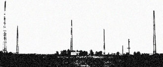
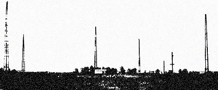
Four-course low-frequency radio-range station showing the five
antenna towers.
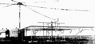
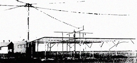
This four-course low-frequency radio-range station is of the
loop type (as are about one-third of FAA's low-frequency ranges; the balance are
5-tower Adcock types). The long-wire antennas in the background are the two loops
which are at 90 degrees to each other and are used to form the actual low-frequency
range courses. The antenna structure in the foreground is a marker antenna array.
This projects a 75-mc. signal directly upward in order to provide a positive "fix"
over the station itself.
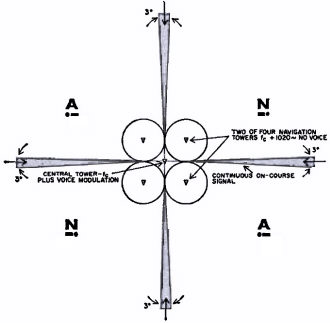
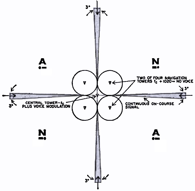
Fig. 1 - Operation of the low-frequency radio-range station.
The simplest radio-range station, shown in Fig. 1, consists of two pairs of vertical
transmitting antennas about 130 feet high set at opposite corners of a square. The
field radiation pattern of each of these pairs is a figure-eight, with the pattern
of one pair displaced 90 degrees from the other. A transmitter is switched from
one pair of antennas to the other to transmit the A on one pair and the N on the
other. These signals are overlapped in time so that along the bisector of the two
figure-eight patterns, where the intensity of the signal received from both pairs
will be equal, the continuous "on the beam" signal is heard over a region with a
width of about 3 degrees. The on-course legs of the beam need not be at right angles
to each other. By appropriate tuning of the antennas, the beam may be directed at
various angles in order to lie along civil airways. The signals transmitted by the
four corner antennas are continuous and contain no modulation. Midway between the
two pairs of towers just described is a fifth tower which transmits continuously
a signal differing in frequency by 1020 cycles from the transmission of the corner
antennas and radiating equally in all directions. It is the 1020-cycle beat between
the center antenna and the four corner antennas which causes the code modulation
which is heard in the receiver.
The central transmitter is voice-modulated for station identification and for
transmission of weather and traffic control information. The federal radio-range
installations shown in the photographs on the facing page are typical of the antenna
installations that are employed.
The chief virtue of the low- frequency radio-range system is its simplicity since
only a low-frequency receiver is required for navigation. However, there are many
limitations, some of them serious. First, the low-frequency radio band is inherently
noisy and highly susceptible to static. The static during a local thunderstorm may
make it impossible for a pilot to aurally follow the on-course signal when he may
need it most. Second, a pilot has no choice in direction of flight since he can
only fly one of the four on-course radials from the station. Furthermore, all courses
are ambiguous. That is, it is impossible to determine in which direction along an
on-course radial a pilot is flying without special maneuvers. Third, and most important,
low-frequency signals tend to bend under certain atmospheric conditions creating
deadly "ghost" on-course signals. This is particularly true near mountain areas.
Radio Direction Finding
Several direction-finding schemes have been devised which allow a pilot to either
"home" on a ground transmitting station or determine his azimuthal direction from
the station. "RDF" (Radio Direction Finding) generally refers to all types of manual
direction finders while "ADF" (Automatic Direction Finding) refers to direction
finders which automatically determine the direction of the transmitting station.
Recently, the term "Radio Compass" has come to mean an automatic direction finder,
and that is the term we will use.
Perhaps the greatest advantage of radio direction finding as a navigational aid
is the fact that this system does not require a special ground transmitting station
for its operation. Theoretically, any station on the ground can be used for RDF
orientation. In practice, however, only standard AM broadcasting stations, the low-frequency
range stations, and special low-frequency beacons are used in order to avoid the
necessity of carrying a large number of receivers covering all frequency bands.
All RDF systems require a directional receiving antenna, a receiver, and a bearing
indicator. Antenna systems used with RDF equipment vary radically in design. The
latest and most sophisticated is Lear's "Gonio Loop," a flat-wound ferrite core
that is electronically, rather than mechanically, rotated. More familiar is the
circular loop about one foot in diameter which is manually rotated. Such a loop
has a figure-eight receiving pattern perpendicular to the plane of the loop. When
the plane of the loop points at the transmitting station, signals are received with
maximum volume. When the plane of the loop is at right angles to the direct line
to the station, signals are received with minimum volume. This minimum volume point,
or "aural null" is used by all direction finders for orientation rather than the
aural maximum point since the null can be determined more accurately. Note that
since the loop plane has two sides, there will be two aural nulls, one on each side
of the loop. For this reason, the simple manual loop is ambiguous since it is impossible
to determine whether the station lies in front or behind the plane of the loop.
This makes it impossible for a pilot to home on a station without special orientation
flying to determine whether he is flying towards or away from the station.

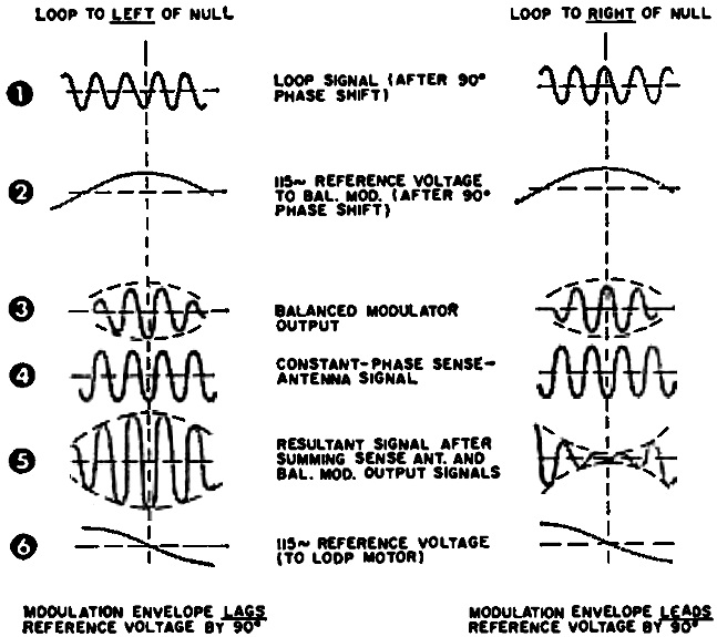
Fig. 2 - Waveforms produced in ADF for various loop positions.
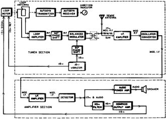
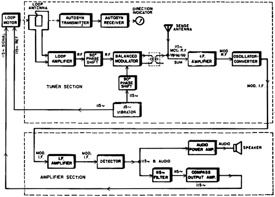
Fig. 3 - Functional block diagram of a typical aircraft
automatic direction finder.
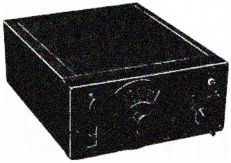
The ADF receiver unit described in the accompanying text.
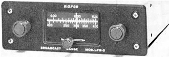
Two-band i.f. unit. 200-415 kc. is for low-frequency ranges.
The mainstay of the single-engine lightplane flyer is a simple two-band receiver
covering the low-frequency radio range and standard broadcast bands and including
a manually rotatable loop for RDF use. With such a receiver, the private flyer can
inexpensively navigate through the use of the radio ranges and RDF, as well as maintain
radio contact with ground traffic-control and weather stations. Most of this equipment
is purchased by the small plane owner as used equipment since simple RDF equipment
is no longer being manufactured.
ADF systems have almost universally replaced the simple manual loop RDF. ADF
receivers are unambiguous, that is, they always point at the station and do so automatically.
Unlike the manual loop, modern ADF loop antennas use a small horizontal ferrite
core upon which symmetrical turns of wire are wound. Like manual loops, these ferrite
loops also have a figure-eight receiving pattern and are inherently ambiguous. Unambiguous
reception is due not to the antenna pattern, therefore, but rather to the method
in which the loop is used in the ADF.
A typical ADF receiver, the Lear ADF-12E, is shown on page 31. In this ADF receiver
the aural null property of the directional ferrite loop and its phase characteristics
are used. As the loop crosses the null point from left of station to right of station,
the output of the loop shifts 180 degrees in phase. This effect is utilized in the
receiver to give "left of null, right of null" sense to the system. A second antenna
is used in the ADF-12E receiver. This second antenna is a long-wire, non-directional
"sense" antenna. Since it is non-directional, its phase is constant irrespective
of the location of the transmitting station and is used to provide a fixed phase
reference against which the loop's phase output can be compared in order to rotate
the loop to a null. When the loop is left of true null its output leads the sense
antenna output by 90 degrees, and when the loop is right of true null its output
lags the sense output by 90 degrees.
Referring to Fig. 3, the amplified r.f. output voltage from the loop is first
phase shifted by 90 degrees in the phase shifter. This 90-degree shift is introduced
as a delay in phase. The result is that if the loop originally led the sense antenna
by 90 degrees, it is now in-phase with the sense antenna as a result of being delayed
in phase. Likewise, if the loop originally lagged the sense antenna by 90 degrees,
it now lags the sense antenna by 180 degrees. These waveforms are shown at (1) in
Fig. 2, which shows important waveforms in the ADF-12E receiver.
This phase-shifted loop signal is now applied to a balanced modulator where it
is AM-modulated at 115 cycles which is produced by a synchronous vibrator from the
aircraft's d.c. supply. Before application to the balanced modulator, the 115-cycle
signal is first phase-shifted by 90 degrees, waveform (2) in Fig. 2. The balanced
modulator simply AM modulates the loop signal carrier close to 100% at a 115-cycle
rate. The balanced modulator output waveform is shown at (3) in Fig. 2.
After being modulated in the balanced modulator, the loop signal is now mixed
with the constant-phase sense antenna signal. The net output produced when these
two signals are mixed depends upon the relative phase between them which, in turn,
depends upon the loop position from true null. If the loop and sense signals are
in-phase (that is, the loop is left of null) the two signals will tend to add together.
When loop AM modulation is at maximum, the net output will also be at a maximum.
However, if the loop and sense signals are 180 degrees out -of-phase (that is, the
loop is right of null) the two signals will tend to subtract and cancel each other.
Therefore, when loop AM modulation is at maximum, maximum cancellation occurs and
the net output will be at a minimum. The result is that the 115-cycle modulation
envelope of the mixed signal either leads or lags the 115-cycle reference produced
by the synchronous vibrator by 90 degrees depending upon the relative position of
the loop. The waveforms produced are shown at (5) in Fig. 2.
The combined r.f. signal now proceeds through a conventional super-heterodyne
receiver. At the output of the detector, the detected 115-cycle modulation is separated
from communication voice frequencies by a filter. The filtered 115-cycle signal
is then amplified in a push-pull compass output power amplifier and is then used
to power the control winding of a two-phase loop motor. The reference winding of
the loop motor is powered by the 115-cycle vibrator supply.
The two-phase loop motor has two important characteristics. First, it develops
maximum rotation torque when its two windings are fed 90 degrees out-of-phase with
each other. Second, the direction of shaft rotation depends upon whether the signal
winding voltage leads or lags the reference winding by 90 degrees. As was pointed
out earlier, the 115-cycle modulation either leads or lags the 115-cycle reference
voltage by 90 degrees depending upon whether the loop is to the left or right of
a true null. The loop motor is connected so that it will rotate the loop which is
attached to its shaft in a direction which moves the loop towards a null. When the
null is reached, there is no output from the loop antenna since it is at the aural
null, hence no signal is delivered to the signal winding of the loop motor and it
stops. In this manner, the ADF-12E receiver automatically rotates the loop to a
true, unambiguous null. A synchro transmitter connected to the loop relays the position
of the transmitting station from the aircraft to a direction indicator on the cockpit
control panel.
A low-frequency aircraft radio direction finder is shown in this photo along
with its indicator.
Several companies manufacture ADF equipment similar to the ADF-12E. Many lightplane
owners, however, cannot afford this equipment which is expensive due to the high
cost of the synchro transmitter and receiver and precision two-phase loop motor
used. Since many pilots are interested in using ADF merely for homing to a station,
the rotating loop antenna can be replaced by a fixed loop whose aural null is straight
ahead. Aero Signal Labs produces the inexpensive RDF-2 "Bird Dog" direction finder
with circuitry similar to the ADF-12E. However, the loop is fixed for homing and
the loop control signal is used to move a meter pointer rather than rotate the loop.
This meter then indicates the airplane's homing heading error. If the pilot keeps
the meter centered by altering his heading in accordance with the deflections of
the meter, he will fly direct to the transmitting station. Direction finders suffer
from the same limitations that radio ranges suffer from and these limitations are
due mainly to the poor propagation characteristics of the low and medium frequencies
used. In a thunderstorm an ADF direction indicator will aimlessly rotate, pointing
at the direction of lightning flashes and discharge static. Unlike the radio-range
system, however, planes using ADF receivers can fly along any radial to or from
a station and are not limited to flying but four courses as they are with ranges.
Furthermore, ADF can be used to obtain running fixes from several stations in order
to establish actual position above the ground. This is obviously not possible with
radio ranges.
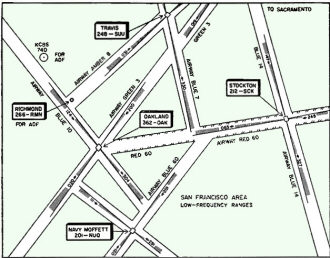
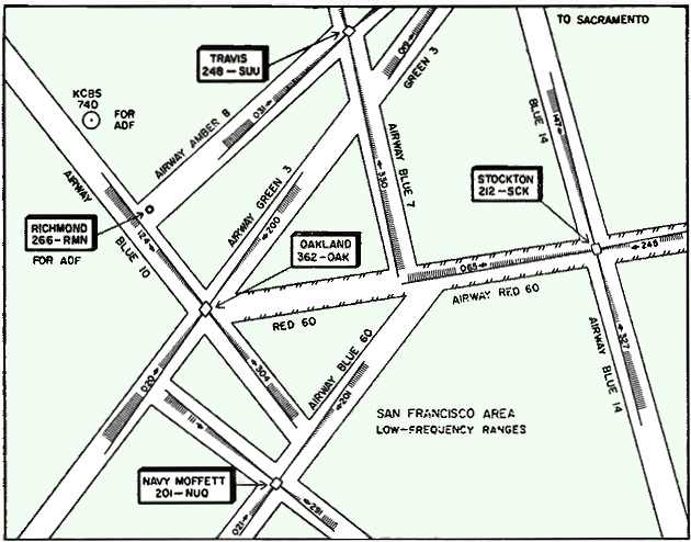
Fig. 4 - Simplified navigational chart showing low-frequency
radio aids.
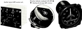
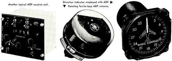
Another typical ADF receiver unit (L). Direction indicator employed
with ADF (C). Rotating ferrite-loop ADF antenna (R).
Navigating
Fig. 4 is a simplified radio navigation chart for the San Francisco area showing
low-frequency navigation aids. Four low-frequency radio ranges are shown; Travis
Range (identified by the letters "SUU" on 248 kc.), Oakland Range (OAK on 362 kc.),
Stockton Range (SCK on 212 kc.) and Navy Moffet Range (NUQ on 201 kc.). The shaded
areas represent the four on-course radials broadcast by the stations. Notice that
nearly all of these radials have been oriented to lie along civil airways.
Also shown are two stations intended for ADF use. Commercial station KCBS (740
kc.) lies almost along airway BLUE 10. A federal low-frequency beacon, Richmond
Beacon (RMN on 266 kc.), is located along airway AMBER 8 to aid in ADF navigation
along this airway.
Suppose an airplane wishes to fly from the east along airway RED 60 to Oakland
Range. Using a low-frequency radio-range receiver, the pilot can tune in Stockton
Range at 212 kc. and fly the east-west on-course signal until he flies over Oakland
Range. With an ADF receiver he can home -in on Oakland Range itself at 362 kc. However,
the fact that he homes-in on Oakland does not guarantee that he is on airway RED
60 since any radial from the Oakland Range can be flown with ADF. In order to stay
on the airway, the pilot must also use his compass to keep his heading along the
airway.
In order to fly from Stockton Range to Travis Range along airways RED 60 and
BLUE 7, an aircraft should have two range receivers, one tuned to Stockton Range
(212 kc.) and the second tuned to Travis Range (248 kc.). The pilot can then fly
along the east-west Stockton on-course signal until the off-course code signal from
Travis Range becomes a continuous tone at the intersection of airways RED 60 and
BLUE 7. The pilot can then turn towards Travis and follow this range signal to the
station.
Flying from Travis to Oakland via airways AMBER 8 and BLUE 10 can be easily accomplished
by an aircraft with a range and ADF receiver. Using ADF the plane can home-in on
Richmond Beacon (266 kc.) and monitor Oakland Range (362 kc.) on the second receiver
until the off-course signal becomes on-course. The pilot can then head towards Oakland
Range along airway BLUE 10.
From these "paper flights" it is obvious that navigation can be made easier for
the pilot if his aircraft is equipped with more than one type of navigation receiver.
For this reason, as well as safety, most commercial airliners carry several receivers,
and installations of dual-ADF's and low-frequency range receivers are common. Furthermore,
this allows the pilot to tune in the weather forecasts which are broadcast by range
stations twice each hour without disturbing the navigational receiver.
Commercial carriers also generally equip their aircraft with dual installations
of VOR, the v.h.f. system of navigation. VOR incorporates all the advantages of
ADF without many of its disadvantages. Next month we shall discuss this modern system
of airborne navigation which is rapidly replacing the ranges and ADF in popularity
for long-range navigation. (To be continued)
Posted January 4, 2023
|