February 1960 Popular Electronics |
 Table of Contents Table of Contents
Wax nostalgic about and learn from the history of early electronics. See articles
from
Popular Electronics,
published October 1954 - April 1985. All copyrights are hereby acknowledged.
|
"Transistor Topics" was a
monthly column in Popular Electronics magazine that helped introduce and
educate readers to/on the relatively new topic of transistor design and troubleshooting.
Transistors were first invented in December of 1948, but it took about a decade
before they were reliable and inexpensive enough to be integrated into a large variety
of products - and affordable to the hobbyist. Editor Lou Garner often presented
questions from readers and answered in layman's terms. This month's question came
from a reader in Bogota, Columbia, which in 1960, was a big deal. Nowadays we take
for granted how small the world is due to the Internet.
Aldens department
store is mentioned, which I remember moving into a shopping plaza next to
Hechinger lumberyard and home
center in Annapolis, Maryland, sometime around 1970.
See other "Transistor Topics" in the series:
January 1956,
December
1957, March 1958,
February
1960, April 1960
Transistor Topics
 By Lou Garner
It's hard to believe, but the transistor's high efficiency and extended life
span have turned out to be "too much of a good thing" in one respect. The transistorized,
solar-battery powered transmitters used in artificial satellites can continue to
broadcast their data for years - which is fine, up to a point. But as more and more
artificial satellites and space probe rockets are launched, the airways will soon
become cluttered with an overwhelming number of transmissions. Since there is a
limited amount of space in the radio spectrum, new satellites may find their broadcasting
being interfered with by signals sent out by satellites launched years earlier.
To prevent this unhappy situation from occurring, the Army Ballistic Missile
Agency has had the Bulova Watch Company design a special "silencer" to turn off
solar-powered transmitters. Assembled in a cube measuring about two inches on each
side, this interesting device weighs about two and one-half pounds. Fully transistorized
itself, it develops approximately one-billionth of one horse-power, yet can be set
to switch off a transmitter automatically after an interval of from zero to nine
thousand hours.
Looking to the future, we can envision larger artificial satellites spaced in
regular orbits around the sun, to be used as outer-space "mileposts" or marker beacons
by interplanetary cargo and passenger ships. Their transistorized transmitters would
be powered either by giant banks of solar batteries or by nuclear "fuel cells" to
insure adequate output power.
Reader's Circuit. Our mailbag frequently includes letters from
POP'tronics readers in South America, Europe, and Africa; and we've even received
mail from as far away as India. Interestingly enough, many of these readers are
experimenting with circuits-and using components - just like those popular with
stateside hobbyists. The circuit in Fig. 1 was submitted by Alexis Pertuz,
a high school student in Bogota, Colombia.
Alexis' circuit is that of a five-transistor AM broadcast-band receiver, with
U.S.-distributed components being used throughout. Essentially a t.r.f. design,
it includes a doubler-type diode detector and a three-stage audio amplifier. A class
AB push-pull output stage is employed, and p-n-p transistors in the common-emitter
arrangement are used in all stages.
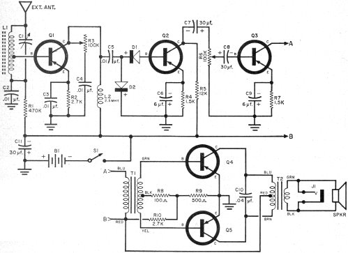
Fig. 1 - Five-transistor AM broadcast-band receiver circuit
submitted by reader Alexis Pertuz, of Bogota, Colombia, includes doubler-type diode
detector and a three-stage audio amplifier.
In operation, r.f. signals are picked up and selected by tuned circuit L1-C1.
A tap on L1 matches the high impedance of the tuned circuit to the moderate input
imped-ance of the r.f. amplifier Q1, assuring minimum tuned circuit loading and
thus maximum circuit "Q" and selectivity. Transistor Q1's base bias is furnished
through R1, bypassed by C2, in conjunction with emitter resistor R2, bypassed by
C3. A small r.f. choke, L2, serves as Q1's collector load, with the amplified r.f.
signal appearing across this coil coupled through C5 to the doubler-type diode detector
D1-D2. The r.f. gain is controlled by bypass capacitor C4 and series resistor R3.
From the detector, the resulting audio signal is amplified by a two-stage resistance-capacity-coupled
audio amplifier, Q2 - Q3. Potentiometer R6 serves as an audio gain control. Large-value
electrolytic capacitors, C7 and C8, are used for interstage coupling to prevent
attenuation of low-frequency signals.
The second audio amplifier stage, Q3, is transformer-coupled to the class AB
push-pull output stage (Q4, Q5) through T1. Output stage bias is furnished by voltage
divider R9-R10 and series base resistor R8. The push-pull stage, in turn, is coupled
to its PM loudspeaker load through impedance-matching output transformer T2. A small
open-circuit jack (J1), across the speaker, is provided for earphone operation.
The d.c. power is furnished by a 6-volt power pack, B1, controlled by a s.p.s.t.
on-off switch, S1, and bypassed by C11.
You can duplicate the receiver using readily available components. Coil L1 is
a standard ferrite loopstick (Lafayette MS-330) and C1 is a small 365-µµf. variable
capacitor. L2 is a common 2.5-mh. choke. All electrolytic capacitors should have
a minimum working voltage of 15 volts.
In the output stage, T1 is an Argonne Type AR-175, with a Type AR-119 being used
for T2. Any standard PM loudspeaker may be employed-a small unit (2" to 4") for
pocket-sized sets, a larger unit (4" to 8") for better tone quality.
Transistor Q1 is an RCA Type 2N147 "drift" type, Q2 and Q3 are G.E. 2N107's and
Q4 and Q5 are RCA 2N109's. Almost any crystal diodes can be used for D1 and D2;
Alexis used 1N48's, but 1N34's or 1N34A's should work as well.
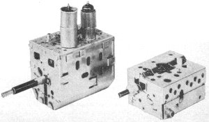 Transistorized TV tuner,
now available from General Instrument Corp., is much smaller and lighter in weight
than old-style tube-operated tuner.
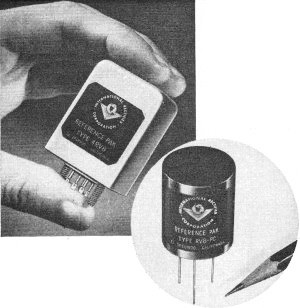
Voltage reference packs made by International Rectifier come
in miniature sizes for printed-circuit board installation and larger sizes for conventional
mounting.
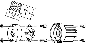
Fig. 2 - Outline sketch and mounting details of transistor heat dissipator
recently introduced by the International Electronic Research Corporation.
The power pack is made up of four pen-light cells connected in series to furnish
six volts. However, Alexis indicates that the receiver will work satisfactorily
on a 9-volt battery without circuit changes.
Neither circuit layout nor lead dress should be especially critical, although
the usual care should be taken to keep signal leads short and direct. The receiver
is suited to either "chassis-type" or "circuit board" construction, depending on
individual preferences.
Although provision is made for an external antenna, Alexis indicates that the
receiver has more than ample gain for the reception of local broadcast stations
using only its built-in "loop" (L1),
Reference Packs. "Pre-packaged" assemblies using semiconductor
components are becoming increasingly popular for many circuit applications. Typical
units are the voltage reference packs manufactured by the International Rectifier
Corporation (1521 E. Grand Ave., El Segundo, Calif.) . These are made in sizes ranging
from miniature units designed for circuit board mounting and providing a single
output voltage to larger units which can operate from a.c. or d.c. sources and can
supply two or more regulated outputs.
Voltage reference packs, in general, supply a known accurately controlled d.c.
output voltage which is maintained constant regardless of variations in ambient
temperatures or in input supply voltages. They are used to replace standard cells
or dry cell batteries in such equipment as digital voltmeters, regulated power supplies,
potentiometric recording instruments, fire control systems, autopilots, missile
guidance control gear, and aircraft instrumentation and communication equipment.
Heat Dissipators. Excessive heat can destroy a transistor. Even
a moderately high temperature can bring about a deterioration in overall circuit
performance. Often, the problem is not so much that of high ambient temperature
as that of getting rid of heat developed within the transistor itself. High power
transistors used near their maximum ratings can become quite warm. To help dissipate
internally developed heat in semiconductor devices, the International Electronic
Research Corporation (145 West Magnolia Blvd., Burbank, Calif.) has introduced a
line of especially designed heat dissipators.
These units are made in a variety of styles to match the most popular transistors
and power diodes. They are available through regular parts distributors and, in
quantity, direct from the manufacturer. A typical IERC heat dissipator, designed
for use with transistors in the familiar JETEC TO-3 "diamond" package, is illustrated
in outline form in Fig. 2.
Overseas News. Semiconductor devices are being used in larger
and larger quantities in the design of foreign-made products. Here are a few spot
items received from our overseas sources.
- Nippon Audio Kogyo Co., Ltd., Tokyo, Japan, is manufacturing transistorized
telephones; each set is designed as an automatic dial master phone and may call
any of ten stations. And Toho Electronics, also in Japan, has introduced a fully
transistorized wirephoto transmitter.
- There are several items from Germany. Dr. med. Noeller, Children's Hospital,
Heidelberg University, has designed a sub-miniature transistorized transmitter which,
with its self-contained battery, measures only 5/32" 1/4" over-all; it is swallowed
by the patient and transmits data on pressure, temperature, and the pH value within
the stomach or intestinal system. Grundig Radio-Werke GmbH, Fuerth/Bay, is producing
a miniature transistorized tape recorder. And a Hamburg firm, Protona GmbH, has
introduced a fully transistorized FM walkie-talkie weighing only 25 ounces. The
Metropolitan Water Board, Sydney, Australia, is using a transistorized indicator
system for low-level sewage pumping stations.
- In Leningrad, Russia, the Aerophysical Institute has reported the development
of a semiconductor thermometer which determines the optimum planting time for wheat
and corn.
Product News. Aldens, a Chicago mail order house, is advertising
a 3-band, 7-transistor portable receiver which sells complete with battery and leather
carrying case for only $49.95. The set tunes the AM broadcast band from 540 to 1600
kc. and short-wave bands from 3.5 to 12 mc.
Motorola, Inc. has announced price cuts in its line of Zener diodes. There is
also news of price cuts on power transistors made by Delco Radio.
The General Instrument Corporation, (Chicopee, Mass.) has started large-scale
manufacture of fully transistorized TV tuners. These units use three Philco micro-alloy
diffused transistors (MADT) and offer a performance comparable to that obtained
from vacuum-tube operated tuners with respect to gain, signal-to-noise ratio, and
image and i.f. rejection. Designed for operation on 12 volts, these tuners require
only 8.5 ma. current.
Before too long, the Raytheon Manufacturing Company, pioneer manufacturer of
low-cost "experimenter's transistors," is expected to announce two new types-p-n-p
units selling for under 90¢ each to the user.
That does it. See you next month.
Lou
Posted August 31, 2022
(updated from original post
on 9/27/2011)
|