|
September 1945 Radio-Craft
 [Table of Contents] [Table of Contents]
Wax nostalgic about and learn from the history of early electronics.
See articles from Radio-Craft,
published 1929 - 1953. All copyrights are hereby acknowledged.
|
This continuation of Part I
of the three-part "Detector Circuits" series covering the basics of diode detectors
delved into some of the specific circuit configurations
and their applications. Here in Part II, author Robert Scott touches on regenerative and superregenerative
feedback "tickler" circuits that are able to detect very low level signals. You
have no doubt heard of "quenching" but how about "squegging?" The nonlinear devices
used in the article happen to be vacuum tubes, so stay away if you suffer from thermionophobia
(a term I just created). Imagine a generic semiconductor diode in place of the
tube if it makes you feel better ;-)
Part I
appeared in the August 1945 issue, Part II in
September, and Part III, the final article in the series,
was published in the October edition.
Detector Circuits
Part II - Hi-Fidelity Triode Detectors; The Plate Rectifier, Infinite-Impedance
Detectors. Grid Rectification and Regenerative Circuits.
By Robert F. Scott
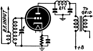
Fig. 1 - A typical plate rectification circuit.
With the exception of the diode, the Plate Detector is perhaps the most commonly
used of the remaining types of detectors. This type of detector may employ either
triode or pentode tubes with equal efficiency. A typical circuit for the plate detector
using a triode tube is shown in Figure 1.
For efficient operation of the plate detector, it is necessary that the grid
of the tube be biased to the point of plate current cut-off and a fairly large signal
be applied to the input circuit. Since the plate current is at cut-off, there will
be no flow of current on the negative halves of the input cycle, but on the positive
portion of the cycle the signal will remove an effective part of the applied bias
and current will flow in the plate circuit. This current will be proportional to
the amplitude of the modulating envelope. When this current is caused to flow through
suitable R.F. filters and a resistive or impedance load, the voltage drop across
this load may be applied to the grid of a following stage for amplification. Since
the major portion of the characteristic curve which is employed is linear, little
distortion will be introduced into the circuit due to the detector.
This slight distortion is due only to the small curved portion at the foot of
the operating curve. Hence, it is clear that the distortion is lessened by the use
of high input voltages.
When a triode tube is utilized as a plate detector, either resistance or impedance
may be employed as the plate load with almost equal effectiveness. The pentode demands
an impedance in its plate circuit, because of the high internal plate resistance.
The pentode is the ideal tube for this service due to the high amplification which
may be obtained from the circuit. Frequency response may be calculated if the tube
is looked at as a class A amplifier tube. Aside from the amplification, which is
possible with this type of detector; there is a definite advantage which makes it
popular in most commercial equipment where sensitivity and selectivity are essential.
This factor is that the plate detector does not load the tuned circuits feeding
it. This type of detector is often called the "linear plate detector."
Infinite-Impedance Detector

Fig. 2 - Standard infinite-impedance detector.
When the ultimate in high fidelity is desired of a detector, it will be found
that the circuit shown in Fig. 2 will meet practically all requirements. A
glance reveals that it seems to be a hybrid between the plate detector and cathode-follower
amplifier. It is also similar to the amplifiers in oscilloscope circuits and the
detectors in some types of vacuum-tube voltmeters. This circuit does not load the
preceding tuned circuits in any manner and its effective input resistance is very
high. Hence this circuit is called the "infinite impedance" detector.
It will be noticed that there is no resistance or impedance in the plate circuit
of the tube. In this case, the resistance in the cathode serves a dual purpose by
supplying the necessary grid bias voltage and acting as a load in the plate circuit.
The loading of the plate circuit is possible because the plate current completes
its circuit via the cathode.
When a modulated signal is applied to the input circuit the positive peaks will
cause the plate current and consequently the current through the resistor in the
cathode circuit to rise. This rise in current causes an additional voltage drop
in the resistor which is equal to the current change times the value of the resistor.
Since the cathode is bypassed only for R.F. currents, the audio currents are forced
through the resistor. The variable voltage drop across the resistor follows the
shape of the modulating envelope. The plate circuit is bypassed for both audio and
radio frequencies to prevent stray currents from entering the power supply.
Inverse Feedback Effect
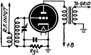
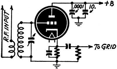
Fig. 3 - Grid-leak is like a diode detector.
It is known that when the load is common to both grid and plate circuits, degeneration
or inverse feedback takes place and the gain of the tube is reduced to a great extent.
This loss in gain is more than compensated for when we consider that one of the
advantages of degeneration is the drastic reduction of all distortion originating
within the circuit to which the feedback is applied.
The resistance in the cathode is so selected as to reduce the plate current to
a low value with no signal input. When a signal is applied plate current will flow
during the positive peaks. This current flowing through the resistor will increase
the bias and thus reduce the gain of the stage. In this case, the feedback ratio
is one-to-one. This limits the gain to unity. For this reason the infinite-impedance
detector is comparable to the diode with identical signal input.
Unlike the diode, this detector is not easily overloaded by a strong carrier
or high modulation peaks because the greater the signal value becomes, the more
effective bias is applied to the grid.
In all of the detectors discussed thus far, rectification of the signal takes
place in the plate circuit. Now we will begin the discussion of a simple circuit
in which the demodulation takes place in the grid circuit. Compare Fig. 3 with
the simple diode circuit with the grid having the action of an anode when it is
allowed to go positive.
Leak-Condenser Detectors
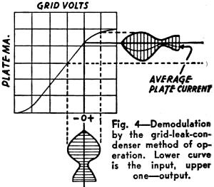
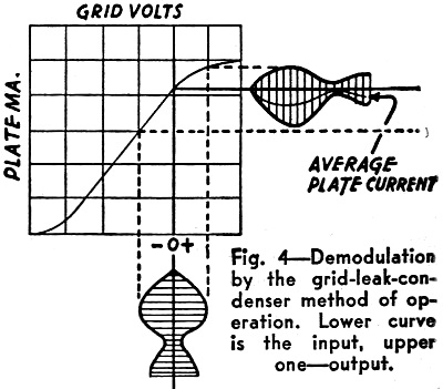
Fig. 4 - Demodulation by the grid-leak-condenser method
of operation. Lower curve is the input, upper one - output.
It will be seen that the only source of grid bias would be from the resistor
in the circuit. When no signal is applied to the input circuit, the plate current
will reach its maximum value for the applied value of plate supply voltage. From
Fig. 4 we observe what happens when a modulated signal is applied to the input
circuit. When the grid is driven positive, the plate current increases somewhat,
but not linearly, due to the curvature at the uppermost end of the grid-voltage-plate-current
characteristic curve. The negative portion of the input cycle reduces the plate
current. This reduction is within the linear part of the curve and the average plate
current for this portion of the cycle will follow the modulation envelope.
Due to the amplification which is available in a multi-element tube, the sensitivity
of this circuit is much greater than that of the diode. This circuit may be adapted
to pentodes as well as triodes but due to the high plate resistance of the pentode,
impedance coupling is the most efficient method of coupling to a following stage.
At normal modulation and signal input values, distortion in the circuit will
be due to the fact that during the positive portion of the input cycle the grid
draws current. This also lowers the sensitivity of the circuit as well as the non-linear
current change due to the positive voltage. This type of detection is often used
in conjunction with regeneration for increased sensitivity.
The values for the grid leak and condenser are carefully proportioned in the
same manner as in the diode detector. The normal value for the grid condenser varies
between .00005 and .00025 mfd. and the grid leak will normally be found to have
a resistance ranging from 100,000 ohms to 5 megohms.
Due to the fact that the grid detector operates without the benefit of any sort
of fixed bias, its voltage handling qualities are much less than if the same tube
were to be employed as a class-A amplifier. The maximum signal voltage that can
be handled by the tube as a detector is approximately one-quarter of the voltage
that could be applied to the tube in straight audio service with identical plate
voltages. This factor will vary somewhat depending upon the amplification factor
of the tube and the value of the grid leak and condenser.
Continuous-Wave Reception
Thus far, the detectors discussed are suitable only for the detection of modulated
signals, but are impractical when it becomes necessary to detect intelligence which
is transmitted by continuous wave transmission, which is used in wireless telegraphy.
This is true because an unmodulated carrier will only produce a D.C. voltage across
the load resistor and this cannot be made to actuate an ordinary amplifier or a
pair of headphones.
When it becomes necessary to receive unmodulated signals, the simplest method
is by the use of the "beat note" or "heterodyne" principle. It is known that when
two alternating signals are mixed there will appear in the output of the circuit
two new frequencies which are equal to the sum and difference of the two original
frequencies. When we apply this method to the detection of a radio signal we employ
a local oscillator which is adjusted to a frequency slightly different from the
frequency of the signal to be received. This signal from the local oscillator will
produce (in the output of the mixer) two frequencies, one of which will be of a
higher radio frequency and the other in the audio range. Since radio-telegraph signals
are sent by starting and stopping the carrier, an audio note will be present in
the output of the mixer when the carrier is being transmitted.
The Regenerative Principle
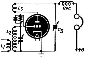
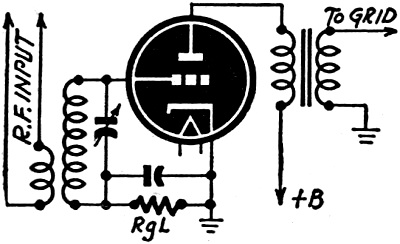
Fig. 5 - Typical grid-leak-condenser circuit.
Fig. 5 shows a grid detector to which has been added a coil which causes
regenerative feedback and makes it possible for the tube to serve as the local oscillator.
L1 and L2 serve as the conventional primary and secondary windings, respectively,
while L3 is the "tickler" or feedback winding. The tickler is so connected that
its voltage is in the proper phase to induce an additional voltage in the grid coil
and thus increase the overall amplification. The condenser C3 is used as the plate
bypass. When it is adjusted so that the tube is on the verge of oscillation, the
tube is most sensitive as a detector of modulated signals. When the feedback voltage
is increased further, oscillations will take place, and when these oscillations
are at their weakest point, the circuit is most sensitive to the reception of unmodulated
code signals. This is called a regenerative detector.
When the tube is oscillating weakly, a further increase of the feedback voltage
will not increase the sensitivity but will actually make the circuit less sensitive
to the reception of weak signals but will make the detector less prone to overloading
and will increase the signal handling capacity. This simple circuit has sufficient
output to operate headphones and when it is well designed and operated, makes possible
worldwide reception of short-wave signals.
One of the disadvantages of the regenerative detector is that when it is in the
state of oscillation it acts as a miniature transmitter and re-radiates a signal
into the antenna. This signal is capable of causing interference to receivers tuned
to the same frequency for some distance. Such interference may be overcome by using
a tuned amplifier stage between detector and antenna.
The Super-Regenerator
While the regenerative detector is one of the most sensitive for the reception
of short wave signals, it is not the best for ultra-high frequency reception because
the circuit losses are very high and because of the fact that the amount of amplification
is limited after the tube goes into oscillation.
If regeneration is increased far enough, the charge on the grid condenser cannot
leak off through the grid leak resistor fast enough to follow the action of the
signal voltage. When it is reduced, the grid condenser retains a large portion of
its charge. Thus the bias of the tube increases and the amount of amplification
is reduced until there is not enough feedback voltage to sustain oscillation. The
oscillations then cease until the charge has leaked off of the condenser. This blocking
is the result of the grid condenser-grid leak time constant.
The blocking action just described is called "quenching" or "squegging," This
phenomenon, when properly applied, gives a tremendous increase in the gain of the
regenerative detector. The grid leak resistor is increased above its normal value.
The tube will be oscillating at a frequency which is due to the LC ratio of the
tuned circuit, but these oscillations will be quenched or choked off at a frequency
that is above the audio range and is determined by the RC time constant. During
the time when the tube is not "quenched," the amplification builds up to an unbelievable
degree. This quenching action causes a pronounced hiss in the output of the circuit
when no signal is present in the input but will decrease in proportion to the strength
of the signal being received.
When this action takes place in a circuit, it becomes a super regenerative detector.
The selectivity of the input circuit is not as good as the straight regenerative
type, but it is much less sensitive to ignition and other man-made types of interference
due to its automatic volume control action, which makes the set most sensitive when
a weak signal is being received. Thus noise pulses of the "shot" type are amplified
much less than the signal and are less disagreeable. Due to the poor selectivity
of this circuit, it makes a good cheap receiver of frequency-modulated signals.
The more swing applied to the FM signal, the greater will be the audio voltage in
the output of the detector.
References:
Fundamentals of Radio, Jordan
Radio Engineering, Terman
Radiotron Designer's Handbook, Smith
Posted April 24, 2023
(updated from original post on 7/31/2014)
|