|
Here is Part 2 of a multi-part
article on radar that was published in Radio News magazine in 1945. Part 1
appeared a month earlier, and the series ran into the Fall. In the interim, World
War II was won and ended by the Allies. Interestingly, a lot of readers wrote
in to the magazine to criticize the divulging of sensitive technical information
on one of the era's most significant developments. Other than being able to generate
quality RF and analog signals (no digitization at this point), the most critical
subsystem of a radar is timing. Without precision accounting of the times of transmission
and reception, and of processing of the information for displaying to the radar
operator, the system is worse than useless. Improper timing will cause confusion
over where the detected target is in both azimuth and range. Positioning your defense
to counter an attack thought to be 10 miles out and due east, when it is actually
2 miles away an approaching from the north could prove devastating. In fact,
one type of radar countermeasure attempts to create just that scenario to thwart
the enemy's defense. This is a very long article concentrating on timing.
Here are the installments available:
Part 1 - June 1945,
Part 2 - July 1954,
Part 5 - October
1945.
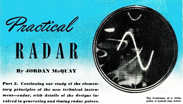
Practical Radar Part 2: Continuing our study of the elementary
principles of the new technical instrument- radar, with details of the designs involved
in generating and timing radar pulses.
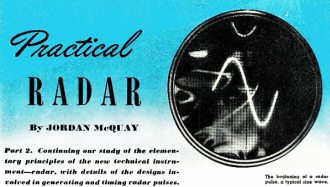
The beginning of a radar pulse, a typical sine wave.
Illustrated by Julian Krupa
By Jordan McQuay
Last month we discussed the elementary principles of radar in the first of a
series of articles on the practical aspects of the amazing new technical instrument,
radar.
We learned that radar employs the principles of electronics, physics, optics,
and high frequency radio. Radar can detect the presence of objects in the sky or
on the sea - such as airplanes, ships, coastlines - and then determine their direction
and range with uncanny precision.
The detection and location of objects is accomplished by means of radio-frequency
pulses of energy, which are transmitted in a narrow beam in any given direction.
The r.f. pulses travel at the speed of light until they strike an object or surface,
and the energy is then reflected or re-radiated in various directions from the object.
Some of this reflected energy returns to the radar set in the form of r.f. pulses
known as echoes.
The determination of the actual range and direction of the object or target is
based on two facts, that r.f. energy travels at the constant velocity of light (about
186,000 miles per second), and that the transmitting and receiving system of the
radar set can be made highly directional.
Since the speed of the r.f. pulses through space is known, the distance or range
between the radar set and the target can be found by multiplying the speed of light
by one-half the time a single radar pulse requires to complete a round trip.
This time will be extremely short, usually only a few microseconds, and a cathode
ray tube is used for accurate measurement of this important time fraction.
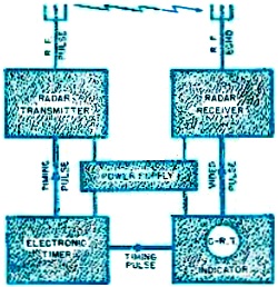
Fig. 1 - Basic block diagram of a radar set. Although many
types of radar equipment are in use, they all operate on the some basic principles.

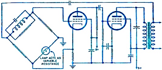
Fig. 2 - Schematic diagram of a typical Wheatstone -bridge
sine wave oscillator.

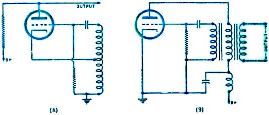
Fig. 3 - Blocking oscillators that may be used as basic
radar pulse generators.
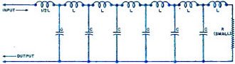
Fig. 4 - Pulse-shaping line consisting of a number of series
coils and shunt condensers arranged in a pi- or H-ladder network. The line is terminated
in a short-circuit.

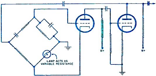
Fig. 5 - A typical Wien bridge which generates a pure sine
wave in the initial stage of the electronic amplifier. The signal is then applied
to a Class A distortionless amplifier to increase the voltage amplitude to a very
high value.
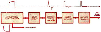
Fig. 6 - An electronic timer employing a multivibrator as
a master oscillator.
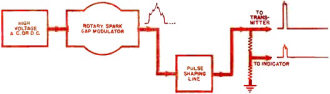
Fig. 7 - Another form of electronic timer is known as a
rotary-spark-gap timer.
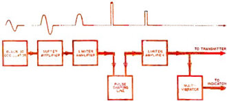
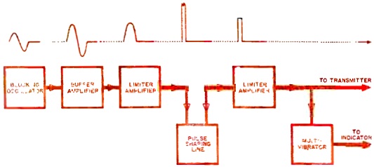
Fig. 8 - A blocking type oscillator used in the initial
stage of the electronic timer.
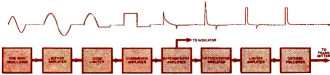
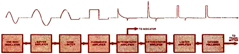
Fig. 9 - A sine-wave oscillator timer. Sine-waves recur
at a fixed frequency equal to the pulse recurrence frequency of the radar set.

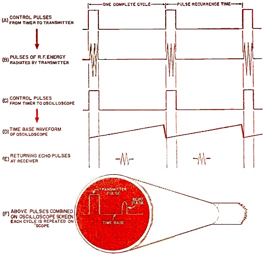
Fig. 10 - The heart of the entire radar set is the electronic
timer. it generates a series of identical impulses which have a certain length or
duration and which occur at an exact and unvarying rate of repetition known as the
pulse recurrence frequency.
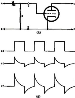
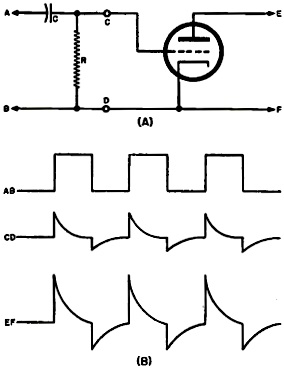
Fig. 11 - Short time constant (RC) circuit used to produce
sharp pulses by differentiation.
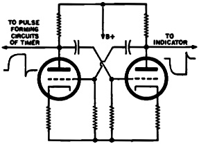
Fig. 12 - Multivibrator circuit.
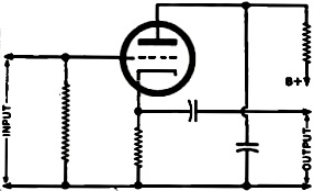
Fig. 13 - Cathode follower circuit.
The radar oscilloscope records the time required for each radar pulse to leave
the transmitter, travel out to any reflecting object within range of the set, and
then return to the radar set. This measurement of time is displayed on a linear
time basis and translated instantaneously into distance, in yards or miles, depending
upon the calibration of the set.
Having determined range or distance, the direction of the target in azimuth (relative
to north) and in elevation (relative to the horizontal plane of the earth) can be
determined by the physical position of the radar antennas.
This gives us sufficient information - range or distance, azimuth or bearing,
and angle of elevation, all with respect to the radar set - so that we can locate
the target accurately in space or on the water.
A basic radar set typical of all radar sets is shown in Fig. 1. The basic components
of the set consist of a transmitter and transmitting antenna, a receiver and receiving
antenna, an electronic timer which synchronizes all of the components, and a cathode
ray oscilloscope for recording the information obtained by the rest of the radar
set.
In practical operation, the transmitter and its antenna send out short bursts
or pulses of r.f. energy at a fast but fixed rate of speed. When this energy strikes
a reflecting object or target, part of the energy returns to the radar set. If the
transmitter is turned off before the returning energy or "echo" arrives, the radar
set can distinguish between the transmitted r.f. pulse and the reflected r.f. pulse.
Then the transmitter can be turned on again and the complete cycle repeated - always
allowing sufficient time for echoes to return from targets within maximum range
of the set. Although slow to describe, the entire out-and-back process takes place
thousands of times per second - due to the extremely high speed of radio waves in
space - and the echoes are displayed on the oscilloscope only a few hundred microseconds
after the original r.f. pulses have been transmitted.
The Electronic Timer
The timing and synchronization of all of the many radar circuits and components
is accomplished by the electronic timer - the true pulse source, the heart of the
radar set.
The electronic timer is responsible mainly for switching the transmitter on and
off at precise and regular intervals. The timer also triggers the oscilloscope time
base every time the transmitter pulses, and performs numerous other control functions
which will be described later.
To accomplish all of these functions, the electronic timer generates an important
voltage; a series of identical impulses, which have a certain length or duration
and which occur at an exact and unvarying rate of repetition. This rate of repetition
is known as the pulse recurrence frequency of the radar set, and is a critical requirement
of the basic control voltage.
The important part played by this basic control voltage can be better understood
by referring to the wave forms shown in Fig. 10. When these control pulses, A, are
applied to the radar transmitter, ultra high frequency radiations, B, take place
for the duration of the controlling pulse from the timer. At the same time, the
same control pulses, C, are applied to the circuits of the oscilloscope, and a linear
time base wave form, D, is triggered off at the start of each complete radar cycle.
Later during each of these cycles, an echo pulse, E, may be received from some distant
target. All of these wave forms are combined on the screen of the cathode ray oscilloscope,
F, and are repeated or retraced on the screen during every complete radar cycle.
From a study of these wave forms (Fig. 10), it will be noted that the control
pulses from the electronic timer are directly responsible for all the synchronizing
action within the radar set, and the determining factor in the timing of each radar
cycle.
The importance of timing in a radar set cannot be overemphasized. The measurement
of time is the chief function of radar - since the measure of elapsed time is found
to be a measure of distance.
It is therefore necessary that the basic control pulses from the electronic timer
be sharply defined, precisely timed in length and duration, and recur at a given
and steady rate of repetition. It's a big job for the electronic timer, one of the
most important in the radar set.
But before we consider how the basic pulse form is generated, let's examine two
outstanding characteristics of the control voltage: the pulse recurrence frequency
and the pulse duration. We can better understand the importance of these two characteristics
by studying the action of the radar transmitter which, it should be remembered,
is controlled by the voltage pulses from the electronic timer.
Timing the Transmitter
We have already discussed how the range of a target is determined by measuring
the elapsed time between the instant when an r.f. pulse is transmitted and the reflected
echo is received.
The transmitted r.f. pulses cannot be very long in duration and they cannot recur
at too short an interval, or the reception of the echo will be obscured by the next
r.f. pulse from the transmitter. On the other hand, it is necessary for the duration
of the pulse to be long enough so that the receiving echo has a definite pattern
in order to differentiate the echo from static, noise, etc. on the oscilloscope
screen. All of these factors influence both the pulse recurrence frequency and the
duration of the pulse.
But the most important factor influencing the frequency of the radar pulses is
a consideration of the maximum range up to which the radar set will operate. And
the most important factor influencing the pulse duration is a consideration of the
minimum range above which the radar set will operate.
There are many different types and Fig. 8. A blocking type oscillator used kinds
of radar sets, each for a particular tactical use: to locate aircraft from the ground,
to locate surface vessels from a shoreline, to locate aircraft or ships from the
air, or for other purposes. In every case the radar set is designed to function
within a certain maximum and minimum range.
First, let's consider the maximum range limit of a radar set, as indicated on
the calibrated scale on the face of the oscilloscope screen. This maximum range
limit may be only several thousand yards on certain sets designed to detect and
locate targets at a comparatively close distance. Other types of radar sets may
be calibrated up to 50 miles, 100 miles, or even higher.
Since ultra high frequency radio waves travel in straight lines with very little
refraction or curvature, the extreme limit of maximum range is not known. But at
very great distances the returning echo is usually too weak to be detected by the
radar set, and atmospheric disturbances create an additional difficulty of interfering
static - which appears as "grass" on the time base of the oscilloscope. It is more
convenient to have a large number of radar stations designed to operate over shorter
ranges, than to attempt to have a single station functioning over extremely great
distances.
We stated earlier that the maximum range of a radar set was an important factor
in the determination of the p.r.f. or pulse recurrence frequency. To illustrate
how the p.r.f. is determined, let's consider a typical example: We are designing
a radar set which we want to detect and locate targets within a maximum range of
45 miles. Therefore,
1 radar cycle = (Range of set in miles)/(1/2 X Velocity of radio waves)
= 45/ - 93,000 (approx.)
= 0.000484 second (approx.)
This result - 0.000484 second - is the time required for one complete cycle of
operations of a radar set with a maximum range of 45 miles. Dividing this fraction
of a second into unity, we can determine the frequency at which pulses must be transmitted
by the set.
p.r.f. - 1/0.000484 sec.
= 2070 ( approximately)
Thus, for a given maximum range of 45 miles it is necessary to transmit about
2070 pulses per second. This p.r.f. must be known so that a returning echo will
not interfere with the succeeding pulse being sent out by the transmitter. In other
words, about 484 microseconds must elapse between the start of one cycle and the
start of the next cycle of operations. This time interval fixes the highest frequency
which can be used for the p.r.f.
In normal operation, the radar antenna system is moving almost continually and
therefore the energy beam may strike a target for a relatively short time. During
this period of time a sufficient number of r.f. pulses should be reflected from
the target to produce a visible indication on the screen of the oscilloscope. Therefore,
the normal speed of the moving antenna system together with the persistence of the
cathode ray screen will ordinarily determine the lowest frequency which can be used
for the p.r.f.
In practice, the pulse recurrence frequency is a value relatively low in the
audio frequency range - generally between 250 and 5000 pulses per second.
The radar transmitter is actually radiating for only an extremely small portion
of the time required for a complete cycle of operations. Referring to our example
above, the set may be radiating during only a few microseconds of the total cycle
of 484 microseconds.
The length or duration of the radar pulse is therefore a small fraction of the
total time required for the pulse to complete a round trip from the radar set to
a target at maximum range.
The actual duration of the pulse determines the minimum range of the set. For,
if the pulse lasts too long an echo from a nearby target will return to the radar
set before the last portion of the transmitted r.f. pulse leaves the antenna, and
the echo from a nearby target will be concealed from view on the cathode ray oscilloscope
by the presence of the transmitter pulse.
Radar sets which detect and locate targets within very close range thus may be
expected to employ a pulse of extremely short duration - on the order of 1 or 2
microseconds. Long range radar sets may use a pulse of much longer duration - 8
to 10 microseconds - since the set is not concerned with targets close to the radar
station.
From this discussion it can be seen that a high degree of precision is expected
of the control pulse from the electronic timer which switches the transmitter on
and off - radiating pulses of r.f. energy.
Generating the Control Pulse
The electronic timer is so called because its function in the radar set is purely
electronic; it is generally concerned with wave shapes of fairly low frequencies
in the audio range. Although these wave forms may later affect the r.f. carrier
of the transmitter and other components of the radar set, the principles of u.h.f.
radio, physics, and optics are noticeably missing from this component of the set.
In the basic block diagram of a radar set (Fig. 1) we indicated the electronic
timer as an essentially simple component. But the timing circuits are probably the
most complicated stages of the entire set, and certainly the most difficult to adjust.
Since wave forms emanating from the electronic timer control all other components
of the radar set, the timing circuits must function with extreme microsecond-precision.
A minute error in adjustment of any part of the timing circuits will be magnified
a hundredfold by the time it reaches other parts of the radar set.
In the basic block diagram (Fig. 1) we also indicated the electronic timer as
a complete and separate component. But in some radar sets the timing circuits may
be integral parts of the transmitter, the indicator, or the receiver.
Regardless of the complexity or the physical location of the timing circuits
in a radar set, however, their function is basically the same: to generate a control
voltage consisting of pulses of a precise duration and recurring at the p.r.f. of
the radar set.
There are two principal methods of generating these control pulses; (1) by means
of circuits providing a recurrent wave shape which is converted into the desired
output pulse shape by the use of distortion and pulse-forming stages, and (2) by
means of circuits which generate the output pulses directly.
While method (1) requires the use of a large number of squaring, peaking, distortion,
and amplifying stages, the output wave form will be sharper, more stable, and more
precise than timing pulses generated by method (2).
It may be assumed, then, that most radar timing circuits consist of several electronic
stages - the number contingent upon the desired degree of sharpness, the amount
of power output required, and the desired stability of the pulse recurrence frequency.
The p.r.f. or pulse recurrence frequency is normally determined in the very first
stage of the electronic timer. Any type of stable oscillator may be used, such as
sine wave oscillator, a blocking oscillator, a ringing oscillator, or a multivibrator.
The shape of the wave from the master oscillator stage is not important, but the
wave must be recurrent at a fixed frequency representing the p.r.f. of the radar
set.
This initial wave form is then applied to a series of distortion pulse-shaping,
and amplifying stages to achieve steep-sided voltage pulses of a given duration.
Diode and triode limiting amplifiers, distortion or differentiator amplifiers, clamping
circuits, and other forms of special stages are employed. Conventional buffer amplifiers
are sometimes used to separate two adjacent and similar functions which might react
on each other, and cathode followers are widely used as impedance- matching devices
to pre vent distortion of the sharply defined, final control voltage.
All of these special types of electronic circuits assist in the shaping of the
output pulse form of the electronic timer without affecting the pulse recurrence
frequency of the wave form.
The number of such stages used in an electronic timer will vary considerably
with different types of radar sets. In some cases these pulse-forming stages may
be reduced to a minimum, or even omitted entirely. But in all such cases - as we
have already noted - the resultant output wave form will not be sharply defined,
and will vary slightly in frequency or pulse duration or both because of lack of
stability. This condition will result in slightly inaccurate range readings on the
oscilloscope. But in some types of extremely portable radar sets, this is not too
objectionable.
For purposes of our discussion, however, we will assume the more normal type
of operation where a fairly high degree of accuracy is required. And the electronic
timer, therefore, is called upon to generate an output control pulse that is stable
in frequency and duration.
Four representative types of electronic timers have been selected to illustrate
means of generating, timing, and shaping the radar control pulse.
Sine-wave-Oscillator Timer
One type of electronic timer (Fig. 9) is known as the sine-wave-oscillator timer,
since the initial stage of the circuit consists of a generator of sine waves. These
sine waves would recur at a fixed frequency equal to the pulse recurrence frequency
of the radar set.
Since the p.r.f. for most radar sets is relatively low in the audio spectrum
- between 250 and 5000 per second - satisfactory frequency stabilization of the
master sine wave oscillator can be achieved without the use of crystals.
Any of the several types of oscillators can be employed to generate sine waves.
The Hartley, Colpitts, Meissner, tuned-grid tuned-plate, or similar circuits
may be used, providing some degree of resistance or impedance stabilization is introduced
into the oscillator stage.
The triode phase-shaft (transitron) oscillator is occasionally used in electronic
timers. The output of a triode is passed back through three successive resistance-capacitance
stages which shift the phase of the original plate signal by 180°. This phase-delayed
voltage is then applied to the grid of the triode, creating and sustaining oscillations.
But the most stable sine wave oscillators for radar use are those circuits employing
bridge stabilization. There are two general types: the Wien-bridge oscillator (Fig.
5) and the Wheatstone-bridge oscillator (Fig. 2), both of which are constant-frequency
devices of high selectivity.
Having generated a pure sine wave in the initial stage of the electronic timer
(Fig. 9), the signal is then applied to a Class A (distortionless) amplifier to
increase the voltage amplitude to a very high value. Sometimes more than one stage
of amplification is necessary for this purpose.
The signal voltage is then applied to a diode limiter, which is connected in
such a way that it acts as a half-wave rectifier - diminishing one-half of the sine
wave cycle. The other half-wave remains at a relatively high voltage amplitude,
however, and is next applied to an over-driven amplifier.
One of the most common of the many distortion circuits applicable to radar is
the overdriven amplifier, or squaring amplifier. The tube itself may be an ordinary
triode or tetrode, operating with normal plate voltage, with the grid biased at
about cut-off. Instead of using a normal input signal voltage on the grid of the
tube, however, the full signal voltage from the diode limiter is applied directly
to the grid. The resulting output wave form is shown in Fig. 9. The flat top of
the wave is caused by a "damping" effect when excessive grid current is allowed
to flow; the flat bottom is due to the plate-current cut-off characteristic of the
tube. The effective grid potential differs from the actual input wave due to the
heavy "loading" effect or "damping" effect caused by the flow of grid current. The
plate voltage variations follow grid changes, and produce steep-front waves approaching
the shape of square waves.
This voltage is then applied to a distortion circuit consisting of a short time
constant (RC) stage followed by an amplifier, as shown in Fig. 11.
When the leading edge of a steep voltage wave is applied to a condenser of an
RC circuit, the condenser charges according to an exponential curve. And the current
in the RC circuit jumps to maximum and then decreases according to an exponential
curve. The resultant voltage drop across the resistor of the circuit likewise jumps
to maximum and then decreases according to an exponential curve.
By tapping off the voltage across the resistor of the short time constant (RC)
circuit, we are able to obtain a peaked wave shape with a sharp, steep leading edge
(Fig. 11). We ignore the diminished negative-going peak, since we are only concerned
with the positive-going half cycle of the peaked wave.
The change which we have performed on the original square-wave voltage is known
as differentiation or peaking. And the short time constant (RC) circuit is sometimes
referred to as a peaking circuit.
The peaked wave form is then applied to an amplifier stage to increase the amplitude
of the peaked wave.
At this point in the timing circuit, shown in Fig. 9, part of the timing signal
is fed directly to the indicator circuits where the peaked wave is used to trigger
the time base of the oscilloscope and to perform other control and synchronizing
functions. But since we are concerned only with the detailed action of the electronic
timer, let's continue with the control signal voltage as it passes through the timing
circuits.
An examination of the peaked wave voltage at the first differentiator amplifier
(Fig. 9) shows that we have created something of a triangular pulse, which we know
will recur regularly at the p.r.f. established by the sine wave oscillator. At this
point in the circuit, the triangular pulse could be applied to the radar transmitter
and it might trigger the transmitter tubes at the proper p.r.f. However, we must
not overlook a second important dimension of the radar pulse: the length or duration.
The triangular output wave of the first differentiator amplifier has no measurable
width at any point along the slope; further, the pulse is much too wide to be of
any practical use. We must, therefore, repeat the en- tire process of differentiation
and amplification in order to produce a much narrower and more sharply defined pulse.
Any desired pulse width can be obtained in the process of differentiation, by
choosing appropriate values for the resistance and condenser in the short time constant
(RC) circuit - which will, in turn, determine the slope of the trailing edge of
the signal pulse.
The output of the second differentiator amplifier can thus be of the required
duration for operation. At this point, however, the amplitude of the pulse is too
great to apply to the transmitter - since it might overload the first amplifier
or modulator units. Accordingly, the pulse is passed through a limiting amplifier
- which may be either a diode or triode - to shear off all unnecessary voltage.
The pulse form is then passed through a cathode follower stage, which merely
serves to match the output impedance of the electronic timer to the input impedance
of the radar transmitter.
Thus, the sine-wave-oscillator timer has generated and formed a series of recurring
pulses - of the proper duration and amplitude, and at the proper p.r.f. - which
can now be used to control the action of the transmitter.
Blocking-Oscillator Timer
Another type of electronic timer (Fig. 8) uses a blocking oscillator in the initial
stage of the timing circuit.
A single-swing blocking oscillator generates a complete audio-frequency cycle,
then pauses briefly before permitting another oscillation to take place. This type
of oscillator (Fig. 3) is somewhat similar in operation to the sine wave oscillator
previously described, except that the oscillations are not continuous.
These interrupted oscillations are generated when the plate and grid circuits
of the master oscillator tube are coupled tightly and the grid acquires a high voltage
at the peak of each cycle. If the flow of grid current causes secondary emission
within the tube, the grid will become more positive with respect to the cathode
and there will be a heavy "damping" effect. This will cause the oscillation to cease
after one complete cycle, and a further oscillation will not take place until the
tube is restored to normalcy.
This form of oscillator is similar to but not the same as a squegging oscillator,
which will be discussed next month.
To produce interrupted oscillations by either blocking or squegging, it is necessary
to have a grid bias RC circuit with a long time constant and have very close coupling
between the plate and grid circuits of the oscillator tube.
The recurrent wave form generated by the blocking oscillator may not always be
a perfect sine wave, but in this case the presence of some distortion is not objectionable.
After leaving the master oscillator (Fig. 8) the wave form is applied to one
or more stages of Class A or Class AB amplification to increase the voltage amplitude
of the wave. An attempt is usually made to protect one half of the cycle from distortion
- to the detriment of the other half-cycle of oscillation. Then, when the wave form
is passed through a limiting amplifier- consisting of either a diode or triode -
the unwanted (heavily distorted) half-cycle of oscillation is removed, as shown
in Fig. 8.
This results in a positive-going high voltage pulse of rather long duration,
which is next applied to a pulse-shaping line - sometimes known as a charged line.
A pulse-shaping line consists of a number of series coils and shunt condensers
arranged in a pi- or H- ladder network, as shown in Fig. 4. The line is terminated
in a short circuit.
When a sudden burst of high voltage is applied to the input terminals of the
pulse-shaping line, electrical energy travels down the line and is then reflected
back to the input terminals. The time required for the energy to travel down the
charged line and back to the input terminals is dependent upon the electrical length
of the line. When the energy is reflected it is reversed in polarity, so that the
resultant wave form at the terminals of the charged line will be a square wave whose
duration is twice the time taken for the energy to travel from the input terminals
to the short-circuited end of the line. It should be noted that the duration of
the output pulse is entirely independent of the duration of the original burst of
voltage applied to the pulse-shaping line. The original burst of voltage merely
serves to actuate the charged line, and the shape of the output pulse depends entirely
upon the electrical characteristics of the line. The output wave form from a pulse-shaping
line is generally of much greater amplitude than the original input burst of voltage.
For the pulse-shaping line to be of practical use, it will be necessary to provide
some means of switching after the original input voltage has been applied to the
line. Otherwise the reflected pulse would return to the plate circuit of the previous
stage. An electronic switch solves this problem, causing the reflected pulse from
the charged line to pass to the next stage of the timer.
It should be noted that the output wave form from the charged line is a sharply
defined, steep-sided pulse having a precise duration. Since the actuating bursts
of voltage occur at the established p.r.f., the output pulse of the charged line
will likewise recur at that frequency.
After the control pulse has passed through a second limiter stage (Fig. 8) to
diminish any excessive amplitude, the pulse is ready to trigger the radar transmitter
- having the required duration, amplitude, and pulse recurrence frequency.
The indicator circuits of the radar set may sometimes be controlled and triggered
by means of a multivibrator, as shown in Fig. 8. The multivibrator completes one
cycle of oscillation each time an output control pulse travels from the timer to
the transmitter, and the action of the multivibrator is con- trolled entirely by
the electronic timer.
Multivibrator Timer
Another type of electronic timer (Fig. 6) uses a multivibrator as a master oscillator,
and then shapes a pulse much in the manner of the sine-wave-oscillator timer previously
described.
The multivibrator finds a wide use - both in timing circuits and in relay and
control circuits. One reason for this is the simplicity with which required timing
signals can be produced for a number of different components. Both positive-going
and negative-going voltage impulses of equal but controllable width can be produced
simultaneously on the two plates of the multivibrator tubes (Fig. 12), which makes
the wave forms ideal for radar requirements.
In the multivibrator timer (Fig. 6), however, we are only considering the positive-going
voltage wave output of the oscillator. The negative-going voltage wave - symmetrical
to the positive-going wave, but 180° out of phase - normally would be passed
to the indicator circuits as indicated.
A conventional, free-running, asymmetrical multivibrator furnishes a slightly
distorted pulse of rectangular shape (Fig. 6) which would recur at a given pulse
recurrence frequency of the radar set. A suitable choice of condenser and resistance
values in the multivibrator circuit will result in any frequency of operation.
Following the master oscillator stage, a delay circuit is introduced in this
particular timer, in order to make the leading edge of the positive-going control
wave coincide with the leading edge of the negative-going wave which went to the
indicator circuits. This delay circuit introduces no physical change in the shape
of control wave, but merely retards the control wave with respect to time - by shifting
the phase 180°.
This wave shape is then applied to a conventional resistance-capacitance short
time constant (RC) circuit which, as we have previously mentioned, results in a
peaked wave form across the resistance. This voltage is fed to the grid of an amplifier
stage, and the output of the differentiator amplifier is applied to a limiting amplifier.
After the amplitude of the pulse form has been limited or reduced to its proper
value, the control pulse - of proper duration and p.r.f. - has been established.
A cathode follower may be used to match the output impedance of the electronic
timer to the input impedance of the radar transmitter. But since a cathode follower
is in reality a distortionless unity-amplifier (Fig. 13), the control pulse will
not be affected by the addition of this isolating stage.
Rotary-Spark-Gap Timer
Timing circuits are not always separate or complete components within the radar
set. They may be located physically with the transmitter, receiver, or indicator
units; or they may be divided among several main components.
One important type of such a timing circuit (Fig. 7) could be contained entirely
in the radar transmitter. It is known as a rotary-spark-gap timer, and directly
controls the action of the transmitter - usually without benefit of amplifier or
modulator stages, since this type of timer is a high-voltage modulating device.
A spark gap consists of two electrodes between which a very high difference of
potential exists. If the spark gap can be made to discharge or conduct, an arc will
take place between the two electrodes and this burst of energy may then be used
to produce radar pulses.
A rotary spark gap consists of one fixed electrode and a number of secondary
electrodes circularly arranged on a metal wheel. As the wheel is rotated, the secondary
electrodes in turn approach the fixed electrode and a brief arc discharge takes
place between the two elements.
The number of spark-gap discharges per second can be varied by changing the speed
of the revolving wheel. The rotary spark gap could, therefore, be used to establish
the basic pulse recurrence frequency of the radar set.
The sudden bursts of energy during the arc discharge are not sharply defined,
however. They usually appear as very ragged and distorted pulses. But they are of
such extremely high voltage, the bursts of energy can be used to shock a pulse-shaping
or charged line - much in the manner of the blocking-oscillator timer, previously
described.
Accordingly, the output impulses from the rotary spark gap are applied to a pulse-shaping
line. This energy is reflected back from the short-circuited charged line as a very
high-voltage pulse having sharply defined steep sides and a duration dependent only
upon the electrical constants of the pulse-shaping line.
The voltage of this output pulse is of sufficient magnitude to trigger or modulate
the radar transmitter directly.
By placing a fairly high resistance between the output and ground (Fig. 7), a
smaller "edition" of the output control pulse can be obtained for triggering the
indicator circuits.
In contrast to the timing systems which we discussed previously, the rotary-spark-gap
timer is inherently unstable. This is generally true of all radar transmitters which
are self-synchronized, transmitters which do not have separate timing circuits.
Related Functions of Timer
The output control pulse from the electronic timer to the radar transmitter is
usually a voltage pulse. The timer is seldom called upon to deliver substantial
amounts of power, since the transmitter usually provides one or more stages of power
amplification before the control pulse is applied to the r.f. transmitter tubes.
However, if the control pulse from the timer were applied directly to the transmitter
tubes, as in the case of the rotary-spark-gap timer just described, the control
pulse from the timer would have to carry sufficient "kick" to modulate the high-frequency
transmitter tubes.
A radar set could be designed to operate over more than one range. In that case
the timing circuits would be suitably changed to permit the instant use of more
than one established pulse recurrence frequency - since every maximum range has
a corresponding optimum value of p.r.f. This change in the timing circuits could
be accomplished by means of switches which alter the value of critical resistors
and condensers. Usually the only change necessary would be in the master oscillator
stage which controls the pulse recurrence frequency of the control pulse.
The electronic timer may be called upon to produce, in addition to the basic
control pulse, any number of special controlling wave forms affecting other components
of the radar set. A square-wave voltage may be required to "block out" a portion
of the oscilloscope time base during a particular portion of the out-and-back cycle
of the radar pulse. If a radar set used only a single antenna for both transmitting
and receiving, it might require a switching voltage wave form from the electronic
timer - to separate the received echoes from the transmitted pulses. It might also
be necessary for the electronic timer to supply the radar receiver with a "blocking"
voltage, so that the first stage of the receiver would not be saturated and damaged
during the brief period when the transmitter is pulsing high-frequency energy. The
indicators of most radar sets usually require special control wave forms from the
timer, in addition to the pulse that triggers the linear time base of the oscilloscope.
These secondary functions of the electronic timer will be discussed in future articles
of this series, and it is sufficient to note at this time that all of these secondary
voltages and wave forms are directly related in phase (time) with the basic control
pulse which modulates the radar transmitter.
Ed. - In a coming article, the practical operation of the radar transmitter will
be considered, with new and important u.h.f. techniques put to a practical use in
radiating the radar pulse into space.
(To be continued)
Posted May 3, 2022
|