|
It took me way too long, but I finally
got the June 1945 issue of Radio News magazine with Part 1 of the
"Practical Radar" series of articles by Jordan McQuay. The opening sentence
said a lot to the readers of the day: "The veil of secrecy has been lifted."
Radar technology was a highly guarded science during World War II, and, along
with its related technology, sonar, is widely credited with providing
Allied forces
the tools needed to eventually emerge victorious against
Axis forces on land and
sea. Yes, Germany and Japan (and
Italy,
but they didn't produce any systems) also had radar and sonar, but American and
British engineers managed to keep a step ahead, providing a major advantage. The
same goes for countermeasure techniques. This very extensive introduction to
radar was followed by four more equally lengthy articles. By the time this
edition of Radio News was
published, the war in
Europe
and Africa was over, and would soon be ended in
Japan, so
divulging "secrets" approved by the Department of War was not a big deal. There
were, however, many readers of this and other publications that were upset about
the information appearing prior to the formal end of World War II.
Here are the installments available:
Part 1 - June 1945,
Part 2 - July 1954,
Part 5 - October 1945.
Practical Radar Part 1: Presenting the basic technical principles of the
most outstanding development of this war - radar.
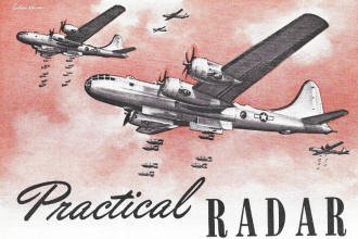 By Jordan McQuay By Jordan McQuay
Additional information on this subject will be published as
censorship restrictions are lifted.
The veil of secrecy has been lifted.
Now, for the first time, some of the basic technical aspects of radar may be
discussed openly - in books, magazines, newspapers - and the secrets of this scientific
discovery made known to everyone.
Millions of words will pour from the printing presses of the nation, screaming
the wonders of radar in high-flown phrases and press-agent adjectives. Meaningless
and long-winded attempts to explain the technical operation of radar already have
made their appearance amid the general claque and fanfare.
Ed. - A pulse of high-frequency radio energy, timed and shaped
by precision electronic circuits, is flung into space. It travels with the speed
of light until it strikes some interfering object - an airplane, ship, or coastline
- and then bounces back, rebounds to d receiver, all within a few millionths of
a second! But in those few microseconds we know of the existence and exact location
of the airplane, ship, or shoreline. For this is radar, the miracle of modern science;
the greatest technical discovery of the war!
But what are the practical facts about radar? Stripped of all its tinsel and
ballyhoo, what are the practical uses of radar equipment? What are the important
fundamentals of radar theory and technique that concern the average radio-man: the
amateur, the experimenter, the radio serviceman, the businessman, the manufacturer?
This is the first article of a series on the basic principles of ultra-high frequency,
of which radar is one. The basic concepts presented here will be developed further
in future issues of Radio News covering, within the limits of Government security,
the practical aspects of radar theory, technique, and operation - the practical
things about radar, the things which you, the radio serviceman, the experimenter,
the businessman should know.
The economic importance of radar should never be minimized. Today it is a major
industry, but radar has an even greater postwar future. With the signing of peace,
radar and aviation will experience jointly an industrial boom of revolutionary proportions.
There will be an unquestionable need for trained and qualified personnel!
Here you will be provided with a complete and comprehensive education in the
technical principles of radar - an education comparable in scope and thoroughness
to the priceless training heretofore given only Government personnel.
Here, then, is the story of radar for the average radioman, the amateur, the
experimenter, the service-man, the businessman. Here is the story of practical radar
for men with an eye toward the electronic future!

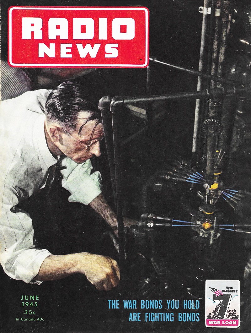
Fig. 1 - Basic block diagram of a radar set. Although many types
of radar equipment are in use, they all operate on the same basic principles.
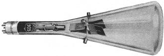
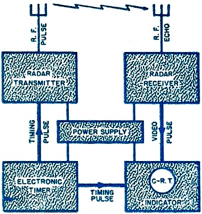
Fig. 2 - An electrostatic cathode-ray tube is used as a typical
radar time-measuring device. Either electrostatic or electromagnetic cathode-ray
tubes are used for this purpose.
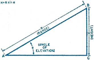
Fig. 3 - Radar equipment determines R and the angle of elevation.
With these two values known, the exact position of any object can be determined
accurately.
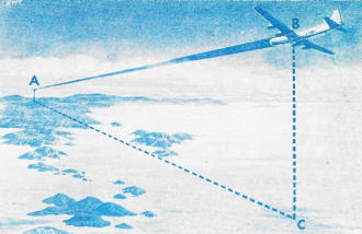
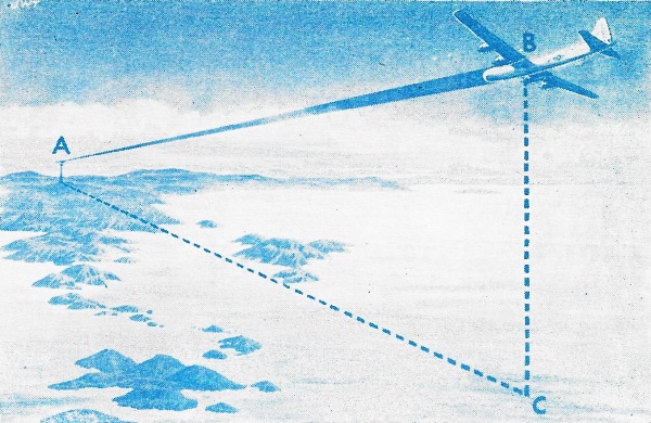
Fig. 4 - The radar beam, when striking the plane, returns
in the form of an echo signal, determining the exact position of the plane. Line-of-sight
is essential, and trees, mountains, etc., will similarly produce echo signals.
Drawn by Radio-News staff artist, Joe W. Tillotson.
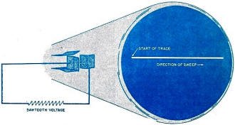
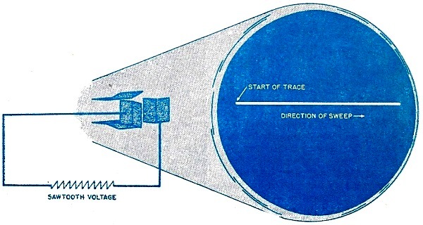
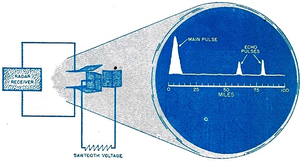
Fig. 5 - Radar oscilloscope with only a time base. A sawtooth
sweep voltage is applied to the horizontal deflecting plates of the oscilloscope,
creating a linear and horizontal time base across the screen of the 'scope.
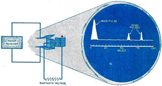
Fig. 6 - Typical radar oscilloscope. The vertical plates
of the cathode-ray tube are connected to the radar receiver. All echo signals detected
by the receiver will be displaced on the oscilloscope and appear as vertical deflections.
We have come to think of a radar set as a unique and very mysterious thing, an
individual piece of secret apparatus performing miraculous feats of location. Actually
there is nothing singular about a radar set. It consists of many units, many circuits,
many separate components - all involving principles of electricity, high-frequency
radio, electronics, optics, and physics.
And there are many types and kinds and sizes of radar sets, from the tiniest
of the ultra-secret "black boxes" installed in bombers to the massive equipment
weighing several tons, used for defending our coastlines.
Why all these sizes; all these kinds of radar sets?
Each for a specific purpose, each radar set designed for obtaining certain types
of information.
The most common use of radar is in the protection and defense of shorelines,
ships, and military or naval installations. Transmitting a protective screen of
radio energy around an installation or area, it is impossible for enemy planes or
ships to attack without being detected long before their actual arrival - regardless
of bad weather or darkness. Thus, cities, islands, and entire coastlines can be
forewarned of enemy attacks, artillery and searchlight crews can be alerted, and
our own fighter planes can take to the air and meet the enemy in battle long before
the enemy planes have even crossed the horizon.
But radar's job is not over when the enemy ship or aircraft has been detected
and located. Radar is used to aim our naval guns, coast artillery, and anti-aircraft
guns with almost infallible precision. Radar-controlled searchlights can follow
enemy aircraft automatically.
Much of the credit for the defense of Britain during the German blitz was due
to the use of thousands of radar sets, installed at every anti-aircraft and searchlight
battery in England! In 1941 larger components of the Italian fleet were sunk in
the Mediterranean in pitch darkness by radar-directed gun batteries aboard British
cruisers. The famous Scharnhorst was destroyed by radar-controlled gunfire from
battleships at an incredible range of many miles. In the Pacific many of our great
naval victories over the Japanese fleet were due to radar control.
But the use of radar equipment is not restricted to land or shipboard installations.
Airborne radar sets perform even more incredible feats of accuracy in detecting
and locating other aircraft and ships at sea, and in directing the fire of aerial
cannon.
Radar is used extensively aboard large bombing planes. One type of radar set
sketches an accurate pictorial outline of the terrain over which the plane is flying
- even when the surface of the earth is hidden by darkness or clouds. Other types
of airborne radar sets are used in fighter planes to track down enemy night bombers,
and radar is used by patrol aircraft to search for enemy vessels.
Since specific objects can be located by means of radar, the radar sets are in
themselves a form of navigational aid. When objects such as shorelines or mountains
can be recognized, the movement of the aircraft or ship can be guided accordingly.
As a further aid to navigation, radar beacons are employed to guide aircraft and
surface vessels. And still another form of airborne equipment, radar altimeters,
is used to measure the exact height of a plane above the earth's surface.
These are only a few of the many uses of radar. Many cannot be discussed until
after the war. But all of them - including the most secret - have a common virtue:
their dependability of operation in all kinds of weather and in darkness.
A Complete Radar Set
Despite the large number of types of radar equipment and the many methods of
tactical employment which we have discussed, it is significant to note that all
radar sets operate on the same basic principles, the same fundamental theory. There
are, of course, minor technical differences between a set designed to control gunfire
aboard a battleship and a set designed to detect and locate enemy aircraft in forward
combat areas. But basically, all types and kinds of radar sets may be reduced in
theory to the simple block diagram shown in Fig. 1.
A complete radar set consists of a radar transmitter and transmitting antenna,
a radar receiver and receiving antenna, a synchronizing device known as an electronic
timer, and a visual means of recording the information obtained by the rest of the
radar set.
The radar transmitter is capable of generating extremely high-frequency radio
waves in short pulses, or "wave trains" of energy, which are radiated into space
by the transmitting antenna. The transmitter does not operate continuously, but
is switched on and off thousands of times per second by means of the electronic
timer.
The recurrent pulses of radio energy are radiated by the transmitting antenna
in a narrow beam in any desired direction. An object or target within range of the
radar set will reflect these r.f. pulses, a portion of the reflected energy returning
to the set in the form of echoes. The echo signals are picked up by the receiving
antenna and passed to the radar receiver where they are detected and amplified.
The echo signals are then displayed on a cathode-ray tube indicator.
By computing the time required for the original r.f. pulse to travel out, strike
the target, and then return to the radar set, it is possible to determine the distance
from the radar equipment to the target. Shortly we shall see how this is accomplished
in detail, by means of intricate electronic circuits capable of measuring time in
millionths of seconds and then translating the result into terms of distance.
The precise timing, production, and radiation of r.f. pulses is known as pulse
modulation - a fairly new radio-electronic term destined to one day become as common
as frequency modulation, for pulse modulation is the key to the secret of radar,
the basis of operation of one of the most complicated high-speed measuring instruments
ever devised by science: radar.
But strangely enough, the fundamental principle underlying pulse-modulation radar
is relatively simple and as uncomplicated as the principle of sound echoes or sound-wave
re-flection.
Analogy of Sound Waves
The sound of a voice echo is a familiar thing. Most of us have at some time shouted
toward a cliff, canyon, or smooth wall, and heard our shout "echo" from the reflecting
surface.
What actually happened, of course, was that sound waves generated by the shout,
travelled through the air until they reached the cliff or smooth surface. Then the
sound waves were reflected, part of them travelling back to the person who shouted.
Not all of the original sound waves returned. Most of them were reflected in
other directions, a few of them may have been absorbed by the cliff or wall. Thus,
the echo that came back to us was always weaker than the original shout.
But, regardless of its strength or intensity, a sound wave always travels through
space at about the same rate of speed: 1100 feet per second. Thus, a given amount
of time elapses between the instant a sound is originated and the instant a reflected
echo is heard. This time interval will be greater if the person shouting is farther
away from the cliff or reflecting surface; the interval will be very short if the
person is standing close to the wall or cliff.
Since we know that the sound waves must make a complete round trip between the
person who shouts and the reflecting surface, and since we know the velocity of
sound in air to be 1100 feet per second, it is easy to determine the distance from
the person to the reflecting wall or cliff.
For example, if we use a stop watch and note that it takes exactly one second
for the echo to return after shouting, the person would be standing about 550 feet
from the reflecting surface; if it takes two seconds for the echo to return, the
distance to the reflecting surface would be about 1100 feet; if it takes four seconds
for the echo to return, the distance would be about 2200 feet; and so on.
The distance from the person to the wall or cliff can be determined by multiplying
one half the elapsed time in seconds by the known velocity of sound waves. This
gives us a means of measuring distance or range from the person to the reflecting
surface by measuring the elapsed time between the transmitted shout and the reflected
echo.
The direction of the cliff or reflecting surface can also be determined by sound
waves. If the person shouts several times, faces a slightly different direction
each time, and each time notes the strength of the returning echo, the direction
of the strongest returning echo will be the direction of the reflecting surface.
Thus, using the simple medium of sound waves, we have determined the direction
of the reflecting surface, and the range or distance from the person to the reflecting
surface.
Use of Radio Waves
Radar sets operate on a principle very similar to that of sound waves.
In radar sets, however, the sound waves are replaced by extremely high-frequency
radio waves, and the entire process of echo reflection is speeded up nearly a million
times!
The high-frequency radio waves are radiated in very narrow pulse-modulated beams
of energy, like flickering pencils of light. Such radio waves are seldom longer
than a few meters and often as short as a few centimeters. But their speed through
space remains the same at any wavelength or frequency-approximately 186,000 miles
per second, the speed of light.
In most respects, the radiation of the r.f. energy is accomplished by a radar
set much in the manner of an ordinary high-frequency radio transmitter. But ,there
are two important differences. The transmitter of a radar set does not function
continuously, but transmits a series of recurrent pulses of energy. And after the
set has transmitted a pulse, the radar set receives its own signal!
Let's consider a single one of these pulses of radio energy. The pulse is radiated
by the radar transmitting antenna in any desired direction and travels in a straight
line through space until it strikes an interfering object or target. Instantly,
the radio waves are reflected or reradiated by the object in many directions. A
portion of these reflected radio waves eventually reaches the receiving antenna
and then the receiver of the radar set. By means of an intricate timing device within
the radar set, it is possible to measure the exact travelling time of the r.f. pulse
from the microsecond it left the transmitting antenna until the microsecond it returned
to the radar set.
Since we know the elapsed time required for the pulse of radio waves to travel
out to the target and back, and since we know the approximate speed of these radio
waves through space (186,000 miles per second) the range or distance from the radar
set to the target can be determined in the same manner we computed the distance
for sound waves.
However, it will be apparent that the elapsed time between the transmission of
a pulse and the reception of an echo will be an extremely short interval. In fact,
this transit time is usually a matter of but a few millionths of a second and therefore
can only be measured accurately by electronic means. The successful use of pulse-modulated
radar systems depends primarily on this ability of the set to measure distance in
terms of time.
The direction of the target from the radar set can likewise be determined much
in the manner of sound waves. Radar transmitting and receiving antennas are highly
directional in themselves. Since the antennas are rotated and moved so that they
always face in the direction of the target being located, the resulting physical
position of the antennas will indicate the direction of the target.
We have only considered the transmission, reflection, and reception of a single
r.f. pulse. In actual operation, the radar set transmits a brief pulse, waits to
receive any echoes from targets within range, then transmits another pulse, waits
to receive echoes, transmits another pulse, waits, and so on. Although the process
seems slow in description, complete transmission - reflection - reception cycles
take place thousands of times per second.
But sufficient time is always allowed between transmitted pulses for echoes to
return from distant targets before another pulse is transmitted.
The radar receiver has no trouble in distinguishing between the original transmitter
pulse and the reflected echo from targets, since only one of the signals is ever
present at one time.
Of course, if a pulse is transmitted into space and fails to strike an object
or target, the radio waves will travel in a straight line out into space and be
lost, and thus go unrecorded by the radar set.
Reflections of Radio Waves
All targets in the path of the pulsed radar beam do not reflect the same strength
of echo signal. The echo signal will vary in strength according to the physical
size of the target, the movement of the target, and the distance from the radar
set to the target.
It is a simple phenomenon associated with ultra-high frequency radio waves, that
a conducting or non-conducting surface of any type, size, or shape will always reflect
some electromagnetic waves. Thus, no target can neutralize or escape from the probing
finger of the radar beam; some portion of the transmitted r.f. pulse will always
be reflected.
If the surface of the target is large and smooth, it will reflect radio waves
much as a mirror or shiny surface will reflect light waves, and most of the radio
energy may be returned to the radar set.
But if the surface of the target is not smooth, the radio waves will be reflected
in different directions, and very little of the original radio energy may be returned
to the radar set.
The latter case is usually true of radar targets. Ships at sea or planes in the
air seldom present a smooth reflecting surface, and therefore much of the energy
reaching the target from a radar transmitter is dissipated by reflection into space.
However, a minute portion of the energy will return to the radar set. And although
this echo signal from the target may be very weak and may vary in intensity, the
sensitive radar receiver usually will be able to detect and amplify the echo.
To obtain a reflected signal of greatest intensity or strength, radar sets generally
employ transmitters of very high power. Since the radar transmitter does not function
continuously, it is possible to generate phenomenally large amounts of output r.f.
power by the use of charged lines and highly efficient output tubes. Power outputs
in the order of one-half to a full megawatt are generated by some radar transmitters,
in an effort to cause extremely stronger reflected target signals.
A number of planes in close formation, or a number of closely spaced ships, will
present a much greater reflecting surface than would a single plane or ship, and
therefore stronger target echoes will be reflected back to the radar receiver.
Echoes will be received, of course, from any sort of object which comes within
the pulsed radar beam. Trees, high buildings, water towers, coastlines, and mountains,
all send back reflections of radio energy. But unlike moving targets such as planes.
or ships, the echoes from trees, buildings, etc., are always fixed and do not vary
in strength.
All of the echoes, moving or fixed, collected by the receiving antenna, are detected
and amplified by the radar receiver and become electronic signals. They appear not
as sound signals as in ordinary radio, but as marks or indications of light on the
screen of a fluorescent cathode-ray tube or oscilloscope. The face or screen of
the scope is permanently marked with a suitable scale, and from the position of
the echo signal on the scope we can determine at a glance all the information necessary
to locate the target.
Locating Targets
What information do we. need to locate the position of a target in space? And,
what degree of accuracy is required?
Let's consider, for example, a ground radar station whose function it is to detect
and locate the position of hostile aircraft. A representative situation is shown
in Fig. 4.
The radar station at A has just detected the presence of an unknown aircraft
B. The immediate concern of the station is to determine the exact position of the
aircraft, and then determine the plane's course and speed.
To locate any object in space, three dimensions are always required. And the
same is true for the aircraft at B. Referring to Fig. 4, we want to know, therefore,
the distance from the radar set to the plane (line A-B), the height of the plane
above the earth (line B-C), and the azimuth or angular bearing of the plane with
respect to the radar station (line C-A). With these three items of information we
can locate the exact position of the plane in space. Certain of these dimensions
are measured indirectly, as we shall see later, but the most important of the three
items, distance, is always measured directly by the radar equipment.
Before we can determine the height and azimuth or bearing of the plane, we must
know the direct air distance from the radar set A to the target B (Fig. 4). This
distance is called the range of the aircraft with respect to the radar station,
and is measured electronically.
The transmitting and receiving antennas of all radar sets are movable. The antennas
can be rotated in azimuth or tilted back at any angle, so that the beam of pulsed
energy may be radiated in any direction. When the transmitting and receiving antennas
are facing full on the target, the indicator of the radar set registers the exact
time (in microseconds) required for the transmission, reflection, and reception
of each echo. The range or distance to the aircraft is computed electronically,
as we shall see later, and the result is displayed visually on a cathode-ray tube,
calibrated in yards or miles. As long as the radar antennas face in the direction
of the target aircraft and echoes are received, the cathode-ray tube will give a
continuous indication of the exact range of the plane.
When the transmitting and receiving antennas were tilted up and .adjusted to
measure the range of the target, each of the two antennas and the radar beam itself
formed an angle with the horizontal plane of the earth. This angle, measured in
degrees or mils, is known as the angle of elevation.
Knowing the range and the angle of elevation, an application of simple trigonometry
will give us the distance from the ground to the plane, since this distance is equivalent
to the length of the side of the "triangle" opposite the known angle of elevation.
Thus, the height of the aircraft can be computed by formula (Fig. 3) when we know
the range and the angle of elevation.
The actual determination of the angle of elevation is not a direct function of
the radar transmitter or receiver. The information is obtained by an electromechanical
arrangement which indicates the angle of elevation in degrees or mils and then automatically
performs the trigonometry indicated in Fig. 3. This gives us an instantaneous reading
of the height of the aircraft, at the same time that the range is being determined
on the oscilloscope.
But we need to know one other dimension in order to locate our target in space:
the azimuth or bearing of the aircraft, with respect to the radar station.
When the transmitting and receiving antennas were rotated to determine the range
of the aircraft, the antennas and the radar beam itself pointed in a certain angular
direction of azimuth or bearing. Since this was purely a mechanical movement, another
electromechanical arrangement can be employed to indicate the direction the radar
antennas point with respect to north. This angle of direction, in degrees or mils,
will be the azimuth or bearing of the target.
Thus, we have determined the three dimensions necessary for locating the exact
position of a target in the air: the range (in miles or yards), the angle of elevation
(in degrees or mils), and the azimuth or bearing (in de-grees or mils). A radar
set supplies all of this information instantaneously and with a high degree of accuracy.
Referring again to Fig. 4, the plane's course and direction of flight can be
determined easily by locating the plane's exact position at frequent intervals and
plotting this information on a map. If the positions of the aircraft are logged
at periodic intervals the speed of the plane can be calculated by simple arithmetic.
When surface vessels are located by means of radar, the angle of elevation is
negligible, of course, and the position of the ship can be determined with only
two dimensions: range and azimuth or bearing. Both of these dimensions are obtained
in the same manner as for aircraft.
Measurement of Time
Determining the accurate range of a target is one of the most difficult
electronic functions of a radar set, since it requires the precise measurement of
time in microseconds.
For this task every component of the radar set must be perfectly synchronized,
and the number of transmitted radar pulses must be rigidly controlled. These functions
are performed by the electronic timer (Fig. 1), the true pulse source for the entire
radar set. The electronic timer may be found to vary in physical size, number of
functions, and even in name - since it is less popularly known as a synchronizer,
modulator, pulse generator, or keyer. But regardless of name or size variations,
the primary purpose of the electronic timer is the origination of a continuous series
of identical control pulses, which occur at an exact and unvarying rate of repetition.
This rate of repetition is known as the pulse recurrence frequency, sometimes
called the p.r.f. The voltage pulse generally recurs several thousand times per
second. But the actual duration or length of the control pulse is extremely short,
usually in the order of but a few microseconds, so there is a relatively long period
of waiting time between the periodic, recurrent control pulses.
When this control pulse from the electronic timer is applied to the transmitter,
the voltage pulse acts as a switch permitting ultra-high frequency oscillations
to take place only for the actual length or duration, of the control pulse. Thus,
the radar transmitter radiates u.h.f. radio energy for a period of time exactly
equal to the duration of the control pulse, and then ceases to function until another
voltage pulse is received from the electronic timer.
During the time period when the radar transmitter is not operating, the radiated
pulse of r.f. energy is moving through space with the speed of light. If the radar
pulse strikes a target, part of the energy will be reflected back to the radar set
in the form of a weak echo. After detection and amplification by the receiver, the
echo is ready to be applied to an electronic device used for accurately measuring
the out-and-back time of the r.f. pulse.
This all-important measurement of time is accomplished by a cathode-ray oscilloscope
which plots the time interval as a function of voltage. Either electrostatic or
electromagnetic cathode-ray tubes can be used for this purpose, and there are many
variations of both types of indicator tubes. But for our purpose, we will use the
simplest and most practical: the electrostatic cathode-ray tube with horizontal
and vertical pairs of deflection plates. Such a typical scope is shown in Fig. 2.
Among the usual and normal control circuits of the radar oscilloscope, there
is a sawtooth voltage generator directly connected to and controlled by the electronic
timer.
This sawtooth sweep voltage is applied to the horizontal deflection plates of
the oscilloscope, creating a linear and horizontal time base across the screen of
the scope, as shown in Fig. 5.
The sawtooth voltage generator is triggered by a control pulse from the electronic
timer, and therefore the linear sweep voltage crosses the oscilloscope screen every
time an r.f. pulse is radiated by the radar transmitter. At the end of the traverse
across the screen, the sweep "flies back" quickly and then, when again triggered
by the electronic timer, the relatively slow sweep of the linear time base is repeated.
In this manner the time base of the oscilloscope is synchronized with the pulse
recurrence frequency of the radar set.
The physical length of the time base on the oscilloscope screen has no direct
relationship to any time value or time scale. But the movement of the sweep is always
linear, and proportional parts of the time base have a proportional relationship
to the total time of the sweep.
The vertical deflecting plates of the cathode-ray tube are connected to the output
of the radar receiver, so that all echo signals detected by the receiver will be
displayed on the oscilloscope. These echo signals appear as vertical deflections
of the time base, as shown in Fig. 6.
Converting Time into Distance
Let's consider the action of the oscilloscope during one complete out-and-back
cycle of an r.f. pulse.
Every time a pulse of radio-frequency energy is transmitted into space by the
radar set, a very small portion of this radiated energy "leaks" through the receiver
and appears as a heavy mark at the start of the oscilloscope time base, as shown
in Fig. 6. This is known as the "main pulse" or "transmitter pulse" and always appears
at the beginning of the time base to indicate that an r.f. pulse has been radiated
by the radar transmitter.
After the transmitter has been turned off by action of the electronic timer,
a relatively long period of quiescence follows - sometimes called the "listening
period." During this quiescent period the time base of the oscilloscope continues
across the screen of the tube at its regular, linear rate of speed. The instant
an echo is received by the radar set, a sudden voltage on the vertical deflection
plates of the oscilloscope causes a sharp deflection in the base line.
The individual actions involved in one out-and-back cycle of the r.f. pulse are,
of course, much too fast to be seen by the human eye. And what we really see on
the screen of the oscilloscope are the time base, main pulse, and target echoes
being retraced thousands of times per second.
Since the time base repeats itself linearly every time an r.f. pulse is radiated
by the transmitter, there is a proportional relationship between the linear sweep
of the time base and the movement of the r.f. pulse through space.
Therefore, the display of information on the cathode-ray oscilloscope is a miniature
record of the transmission and reflection of the r.f. pulses.
When an r.f. pulse fails to strike an object or target, there will be no indication
on the oscilloscope. But all reflected signals will appear somewhere along the time
base of the oscilloscope.
Allowing for twice the travel time due to the out-and-back journey of the r.f.
pulse, the range of the echo target can be determined on the oscilloscope by measuring
the distance along the time base between the main pulse and the echo corresponding
to the target. This distance, as measured along the time base, will be in direct
proportion to the actual space distance separating the radar set and the target.
Therefore, it's not a difficult matter to calibrate the time base in terms of miles
or yards and then attach an appropriate scale to the face of the oscilloscope (Fig.
6) for the quick determination of range anywhere along the time base.
Most radar sets have an established maximum range of operation, and the time
base scale is calibrated to conform to the maximum range. However, this limitation
is arbitrary. Any radar set can be calibrated to record target echoes up to any
given maximum range, merely by changing the slope of the sawtooth voltage wave thereby
changing the speed of the time base sweep to conform to any desired range. For example,
a scope calibrated to detect targets within a range of only 10 miles would have
a fast time base, whereas the same scope calibrated for use up to 250 miles would
have a relatively slower time base.
If several targets at different ranges come into the pulsed radar beam at the
same time, they will each reflect their own echoes which will appear at different
ranges along the time base of the oscilloscope. Referring to Fig. 6, for example,
one target is located at a range of 60 miles and the other target is at 80 miles.
Target echoes never remain stationary on the scope screen. They move in relation
to the actual movement of the target in the air or at sea, and, when the radar set
is installed aboard a ship or plane, the target echoes also move in relation to
the movement of the plane or ship on which the radar set is located.
Posted July 16, 2021
|