|
Robert Taylor claims -
without contention from what I can find - to have invented the concept of
"super-modulation," whereby the normal "splatter" created by greater than 100%
amplitude modulation (AM) can be mitigated through use of specialized circuits.
As with many paradigm-changing discoveries, much was made of super-modulation in
the late 1940s through early 1950s, and then it pretty much dropped off the
charts. The cause might have been that the sophistication of circuitry needed to
keep everything tuned and tracking properly to prevent harmonic and sideband was
deemed not worth the trouble once frequency modulation (FM) came on the scene.
FM quickly gained in popularity due to its relatively high noise immunity; in
fact, many commercial radio broadcast market prognosticators declared AM to be
on life support by the end of the 1950s, with total death to come shortly
thereafter.
Mr. Taylor describes in great detail the concept and circuitry behind his
super-modulation system in a two-part series of articles in 1948 issues of
Radio & Television News magazine. You'll need to put your thinking cap on
when reading these.
Patent #
US2,282,347, "Modulation System," Robert E. Taylor, granted May 12, 1942.
Here is a great bulletin board thread on
super-modulation.
It references the June
1947 QST magazine article entitled, "Overmodulation Splatter
Suppression," by Villard, Jr., O.G., W6QYT. I have not yet purchased that
edition so you will need to get it directly from the ARRL online
archives.
See also "The Taylor 'Super-Modulation' Principle"
Part 1 (Sep. 1948),
Part 2 (Oct. 1948), "Understanding Super-Modulation"
(Feb. 1950)
New method of radio signaling allows greater over-all efficiency with compressed
carrier and emphasized sideband operation.

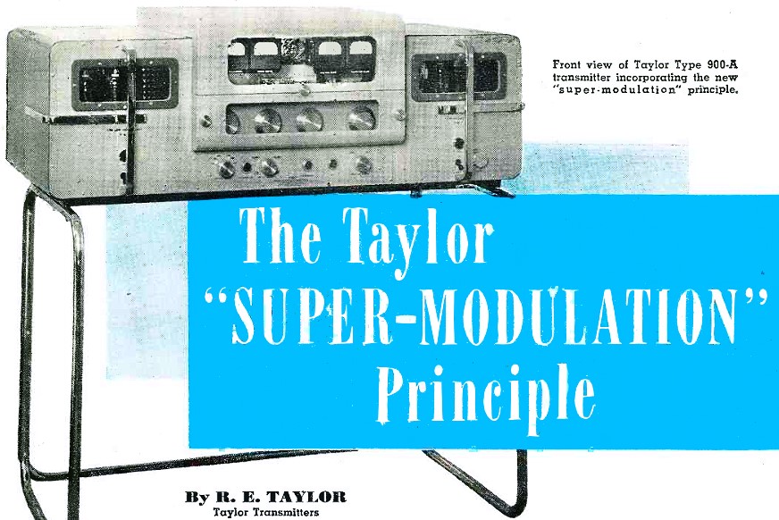
Front view of Taylor Type 900-A transmitter incorporating the
new "super-modulation" principle.
By R. E. Taylor, Taylor Transmitters
Super-modulation, a new method of radio signaling, was discovered some years
past by the author, but its development for general application was delayed by the
war. Several hundred broadcast transmitters were built for the Armed Forces using
the method.
After several years' delay in presenting this new method to the industry, development
has brought the practical application at a time when an improvement is seriously
needed in the amateur and other phases of communication service. Many experimental
transmitters have since been constructed, using this new system. One of the latest,
Type 900-A, a 1 kw. unit, is in service by W6GT, and its operation has been watched
by many with considerable interest.
Circumventing previous sideband power restrictions, and applying heretofore unknown
principles, the super-modulation use of emphasized side bands and semi-suppressed
carrier transmission provides far greater signaling efficiency than was previously
considered feasible.
With more than four times the true sideband power at full modulation, and one-half
or less the bandwidth required in conventional practice, transmission efficiency
is about equal that claimed by some for single sideband operation, and in some operational
respects is superior to single sideband.
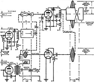
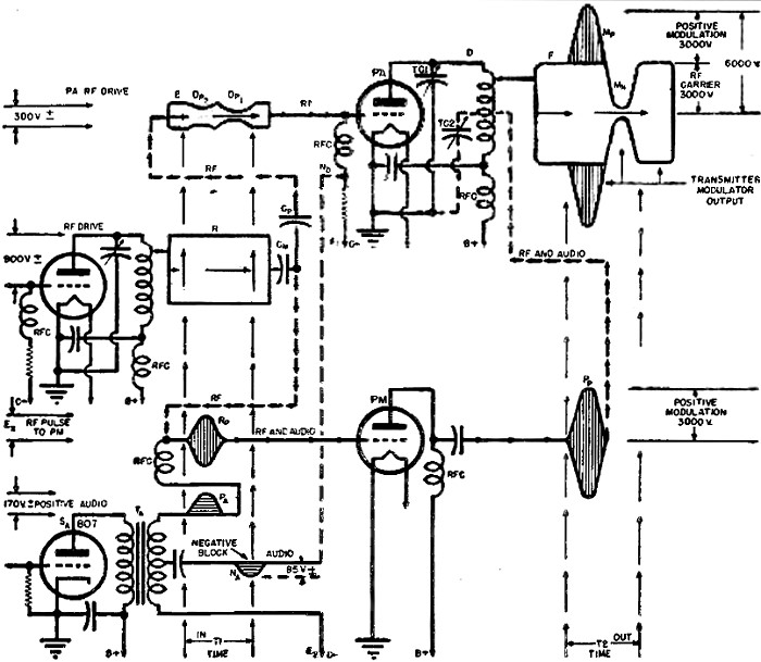
Fig. 1 - Operational example of the "super-modulation" system.
Fifteen to twenty times or more peak power output at full modulation with a bandwidth
of two or three kc. each side of carrier and no spread or splatter, is possible.
Conventional systems are limited to four times or less peak power. Effectively,
this is a sideband or modulation power output increase of from 6 db. upward with
no increase in power input to the carrier production equipment.
In semi-suppression or compression of the carrier power under full modulation,
when the sideband power is driven upward to high level output, the carrier is reduced
at the same time, to allow room for additional sideband power. This also allows
the reduction of the heterodyne or interference level at the receiver end. The reduction
in the noise level is also allowed at the receiver when receiving a super-modulated
signal, due to the compressed carrier and narrow bandwidth. Greater signal voltage
out of a standard receiver linear detector results in 6 db. or more gain over a
conventional signal, without modifications. The first difference that will be noted
is that the signal is so sharp that it is hard for those used to the conventional
broad signals to find. However, when tuned, the signal is louder than anything on
the band.
At the receiver end, the super-modulated signal sounds unusually loud. In many
cases when the b.f.o. is turned on, the carrier heterodyne is barely audible, and
in many instances possible interfering heterodynes from other nearby signals are
not heard at all.
Far better speech quality is provided than in most conventional amateur transmitters,
as the system reproduces the speech in true color without the necessity for limiters
or clippers.
Reception of a super-modulated signal from a 900 A transmitter, in many cases,
is not bothered by a strong signal 2 or 3 kc. away in the band. Two 1 kw. 900 A
super-modulated transmitters were operated under tests about 2 1/2 kc. apart in
the band, using full modulation for maximum sideband power production, with the
"S" meter on the receiver several miles away "pinned" by both signals. Either transmitter
could be tuned in as desired, without interference from the other. Tuning between
the two super-modulated signals resulted in the heterodyne being audible but with
the sidebands of the two signals beating together producing a typical "monkey chatter"
interference. By tuning 1 kc. each side of center between the two signals either
could be readily copied with little interference from the other. This modulation
system has the following advantages:
1. Shows considerable reduction in BCI. Many cases of BCI have been cured by
use of super-modulation because of the lack of "buck shot" and splatter.
2. Provides more than double the over-all operating efficiency of conventional
systems with far less complicated tuning and adjustment.
3. The audio power in the 1 kw. amateur transmitter is only about 8 watts.
4. Provides far greater plate efficiency than conventional practice.
5. The power amplifier and positive modulator tubes, being audio pulsed for operation,
allow greater power input and output. This feature is not new to the radar people
as plate dissipation over a period of time for power output can be engineered and
used to advantage.
6. More db. of talk-power per size and weight as well as more power input than
any other conventional system is offered.
7. About the same power distribution capabilities under full modulation, with
respect to sideband power and carrier, as wide-band FM with 30 kc. total deviation
for 15 kc. audio frequency response.
8. Provides a substantial effect in reducing the noise level of a conventional
receiver for this type of operation.
Sideband power alone, irrespective of how it is generated, is that part of a
transmitted radio telephone carrier wave which conveys the intelligence to the receiver
at the distant point in communications or amateur radio. The undesirable carrier
is one of the greatest contributors to the noise and interference in most receivers.
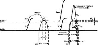
Fig. 2 - Related plate current pulses in new signaling
system.
Thus, the greater the true sideband power produced by the transmitter, the stronger
the received signal with less interference. If the sideband power is a true reproduction
of the modulation, the bandwidth required is about one-half that necessary with
usual high modulation percentages with their attendant distortion, phase shift,
and splatter. Further, if the carrier can be reduced, we find a correspondingly
lowered noise and interference level in the receiver. Theory shows that a true 2
1/2 kc. modulation frequency produces sidebands 2 1/2 kc. removed from the carrier.
In many transmitters the harmonic and distortion produce sidebands 5 to 10 kc. removed
from the carrier.
Therefore, if we utilize only significant and basic sideband components, by means
of appropriate high efficiency production or modulation methods, we wind up with
quite a reduction in bandwidth or about 2 1/2 kc. each side of carrier frequency,
with far greater range of communication because of the increased sideband power,
or talk power of the transmitter.
When we examine conventional transmitter and receiver practice, we find that
the radio transmitter as normally operated along with the receiver has a very low
intelligence transmission efficiency. Hereafter we shall refer to this as ITE. In
other words, ITE represents the true side band or talk power in one sideband produced
by the transmitter.
The broad signal, and limited communication range; of many transmitters using
conventional modulation, is often caused by sideband power limitations.
The basic functioning of this new system is shown in Figs. i and 2 with the simplified
schematic diagram at Fig. 3. Fig. 1 at D represents a conventional power amplifier
capable of about 900 watts input, adjusted for maximum carrier power output of about
700 watts. Proper tuning, matching, and loading is assumed and correct values of
bias, screen, and d.c. plate voltage for the maximum efficiency is provided. This
output tube is indicated in Figs. 1 and 3 as PA. In Fig. 1, the rf. drive power
at E of about 300 volts is supplied to the grid of this tube from the buffer stage
through capacity Cp. The output r.f. voltage shown at F is about 3000
volts or the maximum that may be developed by tube PA within the limits of its input
capability and efficiency.

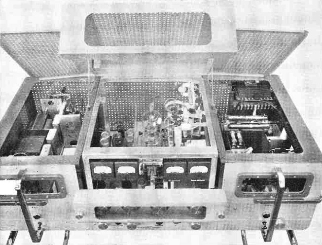
Top view of the Type 900-A transmitter which incorporates "super-modulation"
system.
The plate current pulse of this tube is shown by PL1 in Fig. 2A operating
from base line 1 during the time TP.
Referring again to Fig. 1, when modulation or intelligence is applied to this
r.f. carrier output at F for the sideband power production, the 3000 volts of carrier
is increased to 6000 volts or more for the positive or upward modulation. This same
r.f. carrier of 3000 volts is reduced to almost zero for the negative one-half modulation
cycle. These two points are shown as Mp and Mn respectively.
Common past practice has been to have the increase and decrease of the carrier
controlled and timed so that it follows the waveform of the speech or intelligence
applied, with the upward increase at Mp of equal amplitude and duration
to that of the negative modulation Mn.
In Fig. 1, arrangement is made for a second tube of about the same power input
capacity as the power amplifier tube PA. This is shown as PM, or the positive modulator.
A second output tank condenser TC2 is added for separate flywheel action
of the second tube PM. The output of PM is connected about half way up the output
tank inductor, at that point where the second tank condenser TC2 is connected.
The tank inductance is now slightly reduced to compensate for the added capacity
of TC2, with both condensers TC1 and TC2 ganged
to one control. These condensers are of approximately equal capacity.
Tuning is the same as before with the dual tank condenser adjusted for minimum
dip of the power amplifier tube PA plate current. Tube PM although attached to the
output tank circuit, contributes almost no carrier under no-modulation conditions.
This is shown at PL2 in Fig. 2A above base line 2 during time TM. This
low output is due to the high bias at E2 in Fig. 1, and the low r.f.
drive from the buffer reservoir, through the coupling capacity Cm.
With the positive one-half cycle of modulation, tube PM conducts. Operation is
at a high degree of efficiency and with a very small angle of plate current flow,
as shown by the plate current pulse PL1 in Fig. 2B. In Fig. 1 is shown,
over period of time T2, the additional r.f. power of about 3000 volts
at Pp supplied from tube PM. This is applied to the output tank circuit,
and added to the carrier power present from tube PA, permitting the positive modulation
shown at Mp, above the unmodulated carrier level F.
Mp is then a reproduction in waveform of the r.f. drive pulse Rp
from the r.f. reservoir R, driving tube PM up the desired power output during the
required time.
Triggering control and amplitude of the r.f. drive pulse Rp, as well
as the waveform of the pulse, is effected by the positive one-half cycle of audio
shown at Pa, generated by the audio stage at Sn, and separated
from the negative one-half cycle of audio at the secondary of transformer Ta.
This positive one-half cycle of audio at Pa opens the bias gate from
the r.f. reservoir R during the required time shown at "T1 IN" and corresponds
to "T2 OUT." During this period positive modulation of the carrier at
Mp is developed by power from tube PM.
This is applied directly to and is additive with the carrier power already present
in the output tank circuit. There is no increased plate input to tube PA during
this interval. By allowing operation of the tube PM only during the positive modulation
one-half cycle, a considerable saving in over-all input is permitted. In plate modulation
this same high power modulation energy is used to develop the negative modulation
of the carrier at a considerable waste of power.

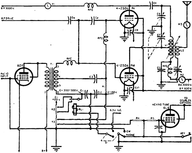
Fig. 3 - Simplified schematic of Taylor system of "super-modulation."
During the function of positive modulation, the average power amplifier efficiency
with respect to carrier, is caused to increase a small degree over that of carrier
level. Power input during this period, to the power amplifier tube PA, is reduced
slightly as shown by TR3 of Fig. 2. The normal carrier power level is
maintained.
As the plate current pulse of tube PM is arranged to effectively extend the plate
current pulse of the tube PA for positive modulation, we have an over-all pulse
of two times or more the amplitude of that of PA at carrier level. This is shown
in Fig. 2A.
During this period part of the carrier power can be supplied by the tube PM as
well as the power for positive modulation. This allows a small reduction in the
plate input and output of the power amplifier tube PA.
The reduction of plate power input and output of the tube PA is effected by a
small reduction in r.f. drive during positive modulation as shown at DP2
of Fig. 1. This is the result of a predetermined impedance ratio between voltage
divider condensers Cm and Cp.
With the higher efficiency and narrow angle of flow of the plate current pulse
at PL2 of tube PM operating from base 2, the over-all pulse of the two
tubes shows a small nick at N1 and N2 of Fig. 2 at carrier
level. This is not important, as the flywheel effect of the output tank serves to
correct this.
With completion of the positive modulation one-half cycle and carrier level restored,
the negative one-half cycle modulation from carrier level to almost zero and back
is the next function. This is effected by reduction of the 3000 volts of normal
carrier to zero and back, as shown at Mn in Fig. 1.
The negative modulation is a duplicate in waveform of the positive modulation.
This negative modulation duplicates in waveform the negative one-half cycle of about
85 volts shown at Na in Fig: 1. The blocking effect of the negative audio
is applied at Nb, and provides the reduced input drive power to the power
amplifier as shown at DP1.
This results in a great reduction of the carrier during the negative modulation
peak at Mn. During this period, tube PM is completely inactive. The negative
carrier modulation function is accomplished with only 85 volts of negative audio
as compared to about 3000 volts required in plate modulation.
Further inspection of the schematic diagram at Fig. 3 shows the basic circuit
to be unusually simple and composed of fewer parts and adjustments than other systems.
Of special interest are the fixed capacitance values at the input of both the power
amplifier and positive modulator, with only conventional tuning and loading of the
output. The r.f. is fed to the power amplifier tube PA through the two fixed condensers
Cm and Cp, with r.f. injection power for the grid of the positive
modulator tube PM supplied from the junction between the two condensers. These condensers
act as an r.f. voltage divider.
Bias for tube PA is taken from the voltage divider R3 and fed through
resistor R1 through the r.f. choke to the grid of the tube. Bias for
tube PM is taken from the top voltage divider resistor R2 with the high
tap for phone and the low tap for c.w., switched by relay RL1 as desired.
This is fed to tap 5 on the secondary of the modulation transformer.
C11 and C12 are 2 μfd. filter condensers across the
high and low voltage bias leads to the tubes PA and PM.
The secondary of the modulation transformer is tapped and delivers 80 to 90 volts
of negative audio through the 2 zμfd. coupling condenser C3. This
is the blocking voltage used in negative modulation.
Tap 3 on the modulation transformer delivers 160 to 180 volts of positive audio
through the r.f. choke for the triggering action of tube PM during positive modulation.
The 807, last stage speech tube, is triode connected and fed to the primary of the
transformer.
110 to 120 volts of audio is developed across the primary for full modulation.
C9 and C10 are screen bypass condensers for the two tubes
PA and PM with the 600 volts for the screens supplied from a fixed and regulated
source.
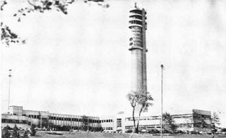
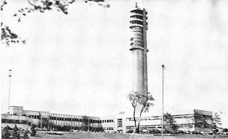
This new 300-foot aluminum-sheathed tower which will enable scientists
to make extensive microwave experiments, was opened recently by Federal Telecommunication
Laboratories, Inc., at Nutley, New Jersey. The laboratories which are housed in
this modern building are research headquarters for International Telephone &
Telegraph.
Although both tubes are fed from the common d.c. plate supply of about 3000 volts,
the power amplifier tube PA is shunt fed through meter M1 and the r.f.
choke to the plate. Condenser C4 is used as a blocking condenser to isolate
the d.c. between the two tubes and at the same time transfer power generated by
PA to the output tank circuit consisting of L1, C6, and C7.
C5 is the r.f. bypass for the cold end of the tank coil. Plate voltage
for tube PM is fed through meter M2 and the r.f. choke through the tank
inductor to the plate of PM. The plate of PM is tapped about mid -point on the tank
coil so that tank condenser C7 may be charged separately as required.
The voltage developed by this condenser will discharge at this point of the coil,
and will be stepped up by the autotransformer action of the complete coil. Operation
of tube PM and its associated components provides at least double the current and
voltage of carrier level, as required for positive modulation.
The inductor L2 is coupled to the tank inductor L1 for
the power transfer to the load or antenna as desired, with condenser C8
for matching of the load, and meter M3 measuring the antenna current.
Also shown is the 6L6 electronic keying tube and associated components, with
switch S1 as the phone-c.w. changeover switch. Bias blocking voltage
for the keying tube is fed from the voltage divider R3. Change of the
phone-c.w. switch to the c.w. position allows several functions at the same time.
The keying circuit to the doubler cathode is opened, the grid of the 807 audio
tube is grounded, and the bias of the positive modulator tube is reduced so that
it may act as a booster for the power amplifier tube PA for increased output in
telegraph service. When a conventional telephone transmitter is used for c.w. the
modulator tubes are of no use.
Adjustment procedure is somewhat different than with other systems inasmuch as
it is simpler. The power amplifier tube has screen voltage of a fixed value, limiting
the dissipation, either in or out of adjustment. The r.f. drive is in the neighborhood
of that required for telegraph service, at a lower value than that required for
plate modulation.
The power amplifier tube actually has its plate input lowered during the positive
modulation, permitting far less r.f. drive power with greater stability and less
strain on the tubes during all functions.
A plate modulated tube takes an increased input during positive modulation, whereas
the power amplifier tube in the Taylor system is allowed a pulsed cooling period
under positive modulation. As the tube is operated at telegraph ratings, it has
a cooling period similar to that of the key up conditions in telegraph service.
The positive modulator tube is not subjected to continuous use as it operates
only on pulses. Its power is delivered directly to and on the carrier without the
troublesome impedance matching modulation transformer.
The r.f. drive and last stage speech tube requirements are conventional. However,
reserve power delivery capacity should be provided as the modulated output of the
system requires full positive peaks of voltage from both the r.f, drive source and
the audio output tube.
Complete and ready for operation, including all power supplies, speech and modulation
equipment, the 900-A unit is easily portable.
The 1 kw. transmitter section of the console, complete on a single main frame
sub-assembly chassis, contains the complete r.f. chain consisting of a 6V6 oscillator,
6V6 doubler, TB-35 buffer-amplifier and the 4-250A power amplifier.
All controls of these stages are front panel operated. A 6L6 keying tube is mounted
under the chassis and is front panel controlled for phone-c.w. operation.
The second 4-250A, as positive modulator and c.w. booster, is located on the
power amplifier tube deck in the center of the chassis. The 807 last speech tube,
modulation transformer, and 6SJ7 speech amplifier tube are located at the left rear
of chassis.
Four sub-panel mounted meters are provided, with two of 0-500 ma. range, for
reading the plate current of the power amplifier and positive modulator. The third
meter of 0-10 volts range, meters the filament of the power amplifier, and the fourth
meter, a 0-100 ma. type, is front panel switched for measurement of the plate current
of all other r.f. stages and the 807 audio stage.
Unusual ease and simplicity of tuning is allowed, as the four front panel controls
tune only the plate circuits of the r.f. stages. This eliminates any adjustment
or tuning of the grid circuits. The only variable coupling circuit in the unit is
that of the output link for the transmission line or antenna.
All r.f. stages are highly biased so that in tuning an out-of-resonance condition
of any of the r.f. exciter stages causes no damage to any of the tubes in the following
stages. The positive modulator is not affected by tuning, as it draws very little
plate current with no modulation.
Plate current off resonance is not excessive as the high bias and the fixed screen
voltage on this tube allows only a slight increase in plate current in the out of
resonance condition.
By providing high fixed bias on all stages, and limiting screen and plate voltages,
we have a pretty safe transmitter, that under a momentarily detuned condition, operates
without damage to tubes or equipment.
The plate tank coils of all the r.f. stages are of the plug-in type, with band
change requiring about 30 seconds. This type of band change was selected after deciding
that maximum efficiency and stability at the high frequencies was more important
than the convenience of bandswitching.
No neutralization is required, and no suppressors are required in either grid
or plate leads in any of the tubes.
The power supplies are of conventional design. A 5Z3 tube is used as a bias rectifier,
a pair of 866A's as rectifiers for the low voltage supply, and a second pair of
866A tubes are used as high voltage rectifiers.
Operational tests of 900-A transmitters using elementary super-modulation as
described so far were as follows : In one case, power input to the power amplifier
tube was 3000 volts at 305 ma., or 915 watts, while the power input to the positive
modulator tube was 3000 volts at 25 ma., or 75 watts. This was a total power input
of 990 watts at non-modulation carrier level.
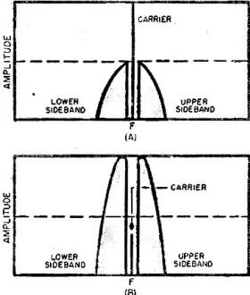
Fig. 4 - Expanded super-modulation possibilities with greatly
increased talk power and reduced interference.
Output was 3.3 amps. into a 72 ohm load, representing 800 watts of carrier output
or a plate efficiency of 80 percent. With modulation, the measured current through
the load was 4.1 amps. or 1210 watts.
The r.m.s. power output increase over carrier level was 410 watts or about the
customary 50 per-cent increase by modulation. The 0.8 amp. increase represented
the usual 22 1/2 per-cent increase over the unmodulated carrier level.
At this modulation level, with narrow bandwidth and other advanced principles
to be described in detail later, input to the power amplifier tube was reduced to
600 watts, represented by a plate voltage of 3000 volts at 200 ma. At a plate efficiency
of 75 per-cent this allowed a semi-suppressed carrier output of 450 watts. Input
of the positive modulator tube was 960 watts on peaks, which allowed, at a plate
efficiency of 85 per-cent, sideband power production of 800 watts, over and above
the 450 watts of semi-suppressed carrier power output of the power amplifier.
Therefore, with the plate power input of 1560 watts for carrier and modulation,
we have in the output during positive modulation, about 450 watts of semi-suppressed
carrier power and 800 watts of sideband power. This is 400 watts in each sideband.
This represents about twice the normal side band or talk power.
Examination of past practice in this system shows why there is such a great difference
in talk power efficiency. Limited carrier and sideband output due to required reserve
tube capacity for upward modulation, is not needed in this system. The direct application
of the positive modulation energy, for the production of sideband power, is in the
form of additional audio triggered r.f. voltage added to the output power. This
eliminates three or more functions necessary in conventional practice, where first
the high power modulating audio must be generated, and then matched and transferred
to the plate of the modulated tube.
Then the modulated tube transfers this energy to the power amplifier plate tank
circuit, which in turn adds the limited sideband power to the carrier power output.
Dispensing with these troublesome connecting links between the modulation energy
and the carrier itself, allows direct carrier superimposition by the modulation
energy for sideband power production.
Further study shows considerable input power wasted in the production of modulation
energy for sideband power in conventional practice. Carrier level plate power input
in case of the low-level system represents wasted power under non-modulation conditions;
about equal to the wasted power input necessary to generate the negative modulation,
in the plate modulated system.
In the new system this power input waste is eliminated as the modulator tube
consumes power only when needed for positive modulation, with high power amplifier
plate efficiency, and little power consumed for negative modulation.
Where the same tube is effectively used to produce both carrier and modulation
in plate modulation, there is no direct connection between the class B modulators
and the carrier. The power amplifier must produce the modulation as well as the
carrier, as the class B modulators simply increase the plate input of the modulated
tube.
Later study of this system in expanded performance and efficiency, with methods
of procedure beyond that presented so far, will be of considerable interest. Fig.
4A shows a conventional carrier of approximately 800 watts or plus 51 db. This is
about that obtained from a plate modulated or NBFM 1 kw. transmitter.
Of the 400 watts of maximum sideband power, that in one sideband is 200 watts
or about plus 45 db. This is 6 db. below the carrier or interference level. Noise
or interfering heterodynes at the plus 51 db. level smother the intelligence or
talk power.
However, in the expanded form of super-modulation, as covered in the following
article, transmission and reception conditions are reversed with the sideband power
level far above the carrier or interference level.
This is accomplished by further increased sideband power and a high degree of
semi-suppression or compression of the carrier, with results somewhat as shown in
Fig. 4b. Non modulated carrier power of about 800 watts or plus 51 db. is, with
full modulation, reduced to about plus 42 db. as at 4B, or 8 to 10 db. below that
of the plate modulated carrier or interference level.
Total sideband power of about 1600 watts then allows about 800 watts at plus
51 db. in each sideband or 6 db. more than in Fig. 4A.
By increasing the sideband or talk power level by 6 db. or more in one direction,
and the simultaneous reduction of the carrier interference level by 6 db. or more
in the other direction, we have a total difference of 12 db. or more in intelligence
transmission efficiency.
Posted May _, 2020
|