|
A few weeks ago I
posted a two-part article on the Taylor super-modulation principle published in
Radio & Television News magazine in 1948. It was a newly announced
technology at the time and was written by its inventor, Robert Taylor. This piece
entitled "Understanding Super-Modulation" appeared a couple years later by another
author, John McCord, where he describes how it works , how to tune super-modulation
circuits, and how it compares to other modulation methods - all conveniently in
"Ham language." Super-modulation is a form of amplitude modulation (AM) that makes
use of carrier and/or sideband suppression to achieve greater efficiency. A panadaptor
- aka pan-adapter, aka panadapter, aka
radio spectrum scope,
aka panoramic adapter - is used to view the RF spectrum across a wide band. Essentially
it is a low budget spectrum analyzer.
Panadapters are now available
as add-on features of software defined radios (SDR).
See also "The Taylor 'Super-Modulation' Principle"
Part 1 (Sep. 1948),
Part 2 (Oct. 1948), "Understanding Super-Modulation"
(Feb. 1950)
How it works, tuning instructions, and a comparison with other modulation methods,
as seen on a Panadaptor.

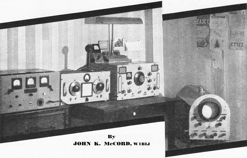
Super-modulated amateur station designed and built by W1BIJ.
(Left to right) Super-modulated final amplifier using 807's, the v.f.o. and driver,
15-tube superhet for ham bands, and the 12-tube Panadaptor used in the signal comparison
tests at the station.
By John K. McCord, W1BIJ
A new method of amplitude modulation has appeared recently. It is simple and
efficient and readily adapted to amateur use. In building a low-power transmitter
using the "super-modulation"* principles and getting it on the air, several major
differences, compared to regular AM methods, were noticed. This article will explain
in practical "ham" language what happens in a super-modulated rig that makes it
so different from conventional AM transmitters. A step-by-step tuning method and
panoramic comparison with other systems will also be covered. Fig. 2 is the home
station final using 807 tubes in super-modulation.
For a basic understanding of super-modulation operation see Fig. 1. The unfamiliar
tank circuit is electrically the same but redrawn to simplify an understanding of
the action. The r.f. tube functions as a regular class "C" amplifier. The p.m. or
r.f. modulator tube, being biased about four times cut-off, doesn't go to work until
you speak into the microphone to modulate. The r.f. tube makes the carrier and the
p.m. tube puts your voice on it by adding r.f. power to the common tank at an audio
rate.

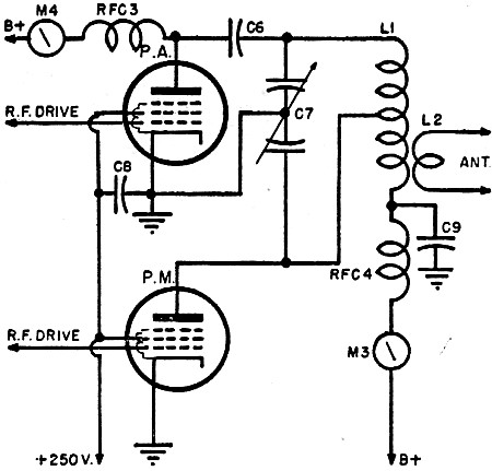
Fig. 1 - The r.f. tube plate is shunt-led and the p.m. plate
series-led to allow use of separate plate current meters. For a diagram of complete
unit and an identification of parts see the schematic shown in Fig. 2.
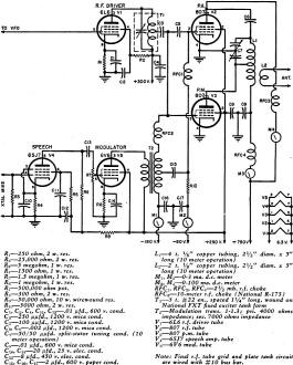
Fig. 2 - Circuit diagram and parts list for the super-modulation
final amplifier and modulator.
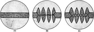
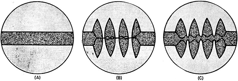
Fig. 3 - How r.f. tube drive should be adjusted to prevent
carrier clipping yet retain high modulation peaks. (A) Carrier only. (B) overmodulation
with clipping. (C) under 100% modulation.
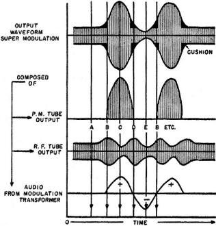
Fig. 4 - Graph showing the super-modulated output waveform and
its separate components, drawn on a common time base.

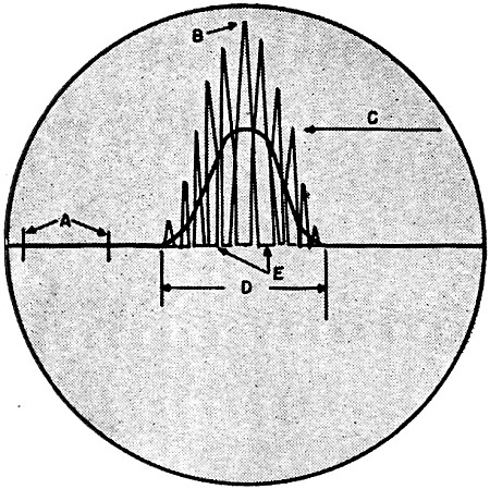
Fig. 5 - Panadaptor image showing method for determining relative
carrier strength, per-cent modulation, and bandwidth. Point "A" is 10 kc. marker.
"B" voice peak. "C" carrier level. "D" bandwidth, and "E" carrier clipped showing
overmodulation. This signal is overmodulated as shown by flattening at "E."
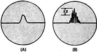
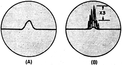
Fig. 6 - (A) Unmodulated regular method AM carrier only. (B)
Same signal 100% modulated, as seen on Panadaptor screen.
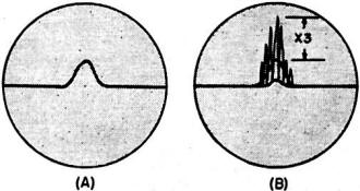
Fig. 7 - (A) Carrier only super-modulated signal. (B) Fully modulated
"super" as seen on Panadaptor. Notice extended positive peaks and suppressed carrier
(lower peak).
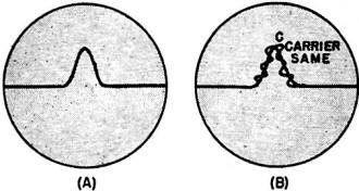
Fig. 8 - (A) NBFM signal without modulation. (B) Same signal
modulated ±3 kc. Notice dead spot at "C."
Fig. 4 shows the super-modulation output waveform and its separate components
drawn on a common time base. As the p.m. tube's fixed grid bias is series-fed through
the modulation transformer secondary, and the r.f. tube bias is in shunt to the
transformer center tap (see Fig. 2), the first audio voltage cycle from the modulation
transformer secondary being a.c., alternately adds and subtracts from the fixed
bias supply voltage. As a result both the r.f. and p.m. tube outputs increase and
decrease accordingly. At time instant "A" in Fig. 4, an unmodulated carrier from
the r.f. tube is shown. At "B," the start of the first positive audio alternation
increases the r.f. carrier slightly to provide a cushion for the coming p.m. tube
operation. At "C" the full peak of the positive audio alternation has cancelled
out the p.m. tube's fixed bias and driven the grid positive resulting in a very
large amount of power released. At this point the p.m. tube demands maximum r.f.
grid drive. By preference less drive is left for the r.f. tube grid and its output
drops, suppressing the carrier. At "D" the p.m. tube's power cycle is ending and
the r.f. tube's carrier rises as a result of returned grid r.f. drive and provides
the final cushioning. At "E" the negative audio alternation adds to the p.m. tube's
fixed bias and the p.m. grid is momentarily about eight times cut-off. Through the
modulation transformer center tap this same negative voltage adds to the r.f. tube's
fixed bias and decreases its output, forming the negative or valley portion of the
output waveform. This completes one cycle of audio voltage from the modulator and
this is repeated for each succeeding cycle. This method of AM modulation has the
following advantages. The positive waveform peaks can be extended to a point only
limited by the p.m. tube's plate saturation point and the r.f. carrier can be suppressed
at the same time. Using regular AM methods, extending the positive peaks beyond
the 1000/0 modulation level would result in a clipped carrier. With super-modulation
the r.f. tube supplies some carrier at all times and fills in between modulation
peaks, preventing carrier clipping regardless of how high we extend the positive
peaks, and it's the peaks that carry the voice intelligence.
Regarding power supply requirements, two plate supplies are not needed. The r.f.
and p.m. tubes do not draw maximum plate current at the same time, so any supply
adequate for a single tube will be OK. Grid bias can be supplied either by batteries
or a separate supply. I tap mine off of the driver power supply bleeder. The r.f.
tube can operate with grid-leak bias, but the p.m. tube must have a fixed supply
and a means of varying the bias voltage over a small range. Tuning the super-modulated
transmitter is quite different from usual procedure and the method is given step-by-step
below. It is assumed bugs and parasitics have been eliminated from your super-modulated
final and enough r.f. drive is available for a single tube. Both finals do not require
maximum drive at the same time. Start with final plate voltage off.
1. Vary the r.f. grid drive and grid bias voltage until the r.f. tube grid draws
1/2 normal drive and the p.m. grid is zero or just starting to draw current. This
balance is important. Run the r.f. tube cool and let the p.m. tube do the work.
2. Closely couple a dummy antenna to the final tank and switch on plate voltage.
The r.f. tube should load normally like a c.w. rig with the key down. Reduce grid
drive rather than antenna coupling to decrease loading. The amount of coupling affects
the tank impedance into which the p.m. tube works.
Keep the r.f. tube running cool at about half c.w. rating, but enough to prevent
carrier clipping during modulation. An oscilloscope check will show the right point.
3. Now apply modulation while increasing the audio gain. The p.m. tube grid and
plate current should both kick upward to high values. The r.f. tube grid and plate
current should show a downward movement, indicating carrier suppression. My 807
p.m. tube shows plate current peaks of 80 to 100 ma. and over. As the meter indicates
an average value, the true peak current is about twice that shown.
4. Disconnect the dummy antenna and load the regular antenna to approximately
the same tuning values.
The oscilloscope pattern of Fig. 3 shows how the r.f. tube drive should be adjusted
to prevent carrier clipping and still retain high modulation peaks. The vertical
scope plates were directly link-coupled to the final tank which was loaded with
the dummy antenna. Warning - If scope is left coupled to tank when using antenna,
r.f. may be fed to the power lines or the connecting leads may radiate, causing
TVI, etc., so check this point carefully.
Checks have been made using a 5-inch Panadaptor to compare super-modulation waveforms
with other signals on the air. The human ear is quite unreliable, even though we
all use it for this purpose. Being logarithmic in function and having poor retaining
qualities we shelved it along with the average receiver "S" meter and found the
Panadaptor to be a decided improvement. Using this visual method small changes in
both carrier and modulation could be seen. A change in amount of modulation not
noticed by the ear can make a real difference in signal-to-noise ratio at a distant
receiving location. It can mean the difference between being readable and not readable.
The Panadaptor shows this difference. Fig. 5 is a mock-up waveform showing method
used to determine relative signal characteristics with the panoramic image.
An average regular-method AM signal on the air appears as shown in Fig. 6. Notice
that the modulation peaks extend just to twice the carrier height without modulation,
and recede to the zero base line. This represents 100% modulation. Extending the
peaks higher would also make the bottom peaks go lower which they can't do without
hitting the zero base line and clipping the carrier. Fig. 7 shows a super-modulated
signal of about the same power or pip height. Notice the positive peaks extended
to three times the unmodulated carrier level, yet the carrier is a long way from
being clipped. The carrier has even been suppressed to minimize heterodyne tendencies
with other carriers. This is still amplitude modulation, but with greatly extended
positive peaks. Fig. 8 is an average. NBFM signal with narrow deviation, and no
splatter when received on an AM receiver. The amount of voice power is small and
even using a discriminator for correct reception results in low audio content because
of the small deviation allowable.. Wideband commercial FM stations, of course, are
very efficient. NBFM has many advantages, but voice efficiency is low. It is evident
that super-modulation delivers far more "talk-power," as Mr. Taylor calls it, than
any of the other types of signals shown. Perhaps some day we may report a received
signal as: "Fine business OM or coming in 10 db. over 9 on my Panadaptor. Your modulation
is about 80% and your bandwidth is 8 kc." This report would give the operator real
information.
While operating a super-modulated transmitter some major differences were noted
compared to the operation of a conventional plate-modulated AM rig.
1. Using regular AM methods the final r.f. plate meter should not vary with modulation.
With super-modulation it should, and does, vary. In fact, they vary, both the r.f.
and p.m. tube plate milliammeters. If they don't, you are not modulating.
2. When receiving a regular method AM signal the "S" meter indicates carrier
strength. A strong movement of the needle with modulation could indicate overrnodulation.
With super-modulation a large needle movement is normal, indicating extended positive
signal peaks. On one transmission check with super-modulation the "S" meter read
S-9 with the carrier only and reached 15 db. over on peaks. "S" meters are relative
indicators only and should not be depended upon for ac-curate measurements.
3. In modulating the usual plate-modulated AM transmitter, an audio power equal
to 50% of the r.f. final stage power is required of the modulator. With super-modulation
the modulating power is r.f., not audio, and is supplied by the p.m. tube. A comparatively
small amount of audio power is sufficient to trigger the p.m. tube into releasing
its power into the common final tank circuit.
When receiving super-modulated signals on a conventional receiver equipped with
a.v.c. the background noise will tend to rise during periods of reduced carrier.
This action will cause no difficulty in the majority of cases unless the carrier
suppression is severe. In any event, the turning off of the a.v.c. will result in
a much more readable signal when this occurs. It is advisable to try both ways.
I have heard super-modulation referred to as a form of pulse modulation and unlawful
for amateurs. Super is definitely amplitude modulation. The word "pulse" could just
as readily describe the driving power to a pair of class "B" modulators. One works
as much on a pulse basis as the other. Super has been referred to as a form of low-level
grid modulation, perhaps as a result of a hasty glance at the schematic diagram.
Because the modulation is added to the carrier in the final transmitter stage, this
insures its being high level. Although audio is applied to the tube grids, the p.m.
tube is not a class "C" amplifier making a constant carrier as would be found in
grid modulation systems. The p.m. tube is actually an r.f. modulator and can be
thought of as taking the place of the usual class "B" modulators used in regular-method
AM transmitters. In conclusion, super-modulation represents real efficiency. The
p.m. or modulator tube is dead until you speak. Then it releases r.f. power at an
audio rate only half of the time, on the positive audio voltage alternations. On
the negative alternations it is cooling. Expensive audio transformers are not required.
It's still cheaper to obtain say 100 watts of r.f. power than the same amount of
audio power.
* Taylor, R. E.: "The Taylor 'Super-Modulation' Principle," Radio & Television
News, Sept. and Oct., 1948.
Posted June 12, 2020
|