|
Here is the final installation
of a-22 part series entitled "The Saga of the Vacuum Tube," by Gerald Tyne, that
appeared in Radio News magazine in 1946. Part 1 was printed in March
1943. The collective contents, which covered the development of the vacuum tube
from its conception to the end of World War I, could have been published as
a stand-alone book. Author Gerald F. J. Tyne presented the series to trace
the development which took place up to the end of World War I along a particular
branch of the network of roads which led to the modern radio tube. He traced the
evolution from studies of the interactions between heat and electricity as pursued
by the early philosophers and by the physicists who followed them (Lee de Forest,
et al). These limitations have been adopted in an attempt to report the work done
in the years where there is a dearth of readily available published material. At
the time this final article was written near the end of World War II, great
strides had been made in vacuum tube technology that not only helped secure victory
for Allied forces, but served as a springboard for fueling a booming economy in
the post war years as households transitioned from a wartime to a peacetime existence
that saw unparalleled growth in creature comforts, many of which used vacuum tubes.
See list of all 22 parts at bottom of page.
The Saga of the Vacuum Tube - Part 22

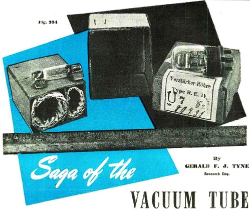
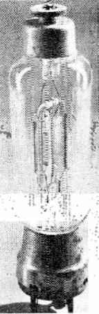
Fig. 234 - RE11 tube with ballast resistor. Photograph courtesy
Bell Telephone Laboratories.
By Gerald F. J. Tyne
Research Engineer, N. Y.
Part 22. Concluding article of a historical series which has covered the development
of the vacuum tube from its conception to the end of World War 1.
Not long after the EVE173 tube was put into production the system of nomenclature
was changed and German receiving tubes were denoted by the prefix RE (= Rohre Empfanger),
transmitting tubes by RS (= Rohre Sende), and two new prefixes came into being RG
(= Rohre Gleichrichter) for rectifiers and RV (= Rohre Endverstarker) for output
tubes.312
Probably the first of these tubes to be made in any quantity, 250 per day in
1918,313 was the RE11, shown in Fig. 234. This tube like most of its predecessors
was used with an iron wire ballast resistor in the filament circuit and one of these
ballast resistors is also shown in the figure_ This tube had a tungsten filament
of about the same characteristics as the 52 EVE173 (.55 ampere at 2.8 volts), but
operated at an anode voltage of 40 to 70 volts and had an amplification factor of
8 and mutual conductance of 120150 micromhos, slightly higher than that of the EVE173.314
It was a general purpose tube.
Another general purpose tube, bearing a closer resemblance to the EVE173, was
the RE16 shown in Fig. 244. This was used chiefly as a detector for c.w. work.315
The extent of its use may be gauged by the fact that in the summer of 1918 Telefunken
was producing them at the rate of 1000 per day.313 It had a filament which took
0.50.6 ampere at 4.0 volts. The usual anode voltage was 65 and the mutual conductance
about 200 micromhos, the internal resistance being about 24,000 ohms. This tube
had about the same anode characteristics as the French tube described in the preceding
installment although it required less filament power. The normal anode current was
about 1 milliampere.
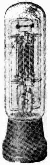
Fig. 235 - Telefunken RS1 vacuum tube. Reproduced from Telefunken
Festschrift 1928.
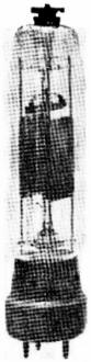
Fig. 236 - Telefunken RS5 vacuum tube. Photograph courtesy
R. McV. Weston and Electrical Communication.
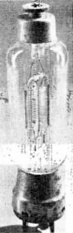
Fig. 237 - TKD ST12 vacuum tube.
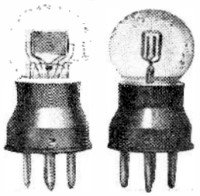
Fig. 238 - Huth LE219 vacuum tube, front and side views. Reproduced
from Nespers' "Der Radio Amateur "-1924.

Fig. 239 - LeftSeddig vacuum tube. Filament 0.56 ampere at 2.8
volts. Right Auer receiving tube.
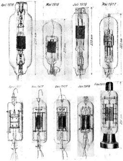
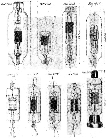
Fig. 240 - Development of Telefunken RS17 vacuum tube. Reproduced
from Niemann's "Funkentelegraphie fur Flugzeuge" 1921.
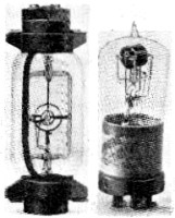
Fig. 241 - Development of the SS (Siemens Schottky) type vacuum
tube. Reproduced from "Veroffentlichungen aus dem Gebiete der Nachrichtentechnik"-1935.
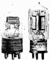
Fig. 242 - Left RE20 vacuum tube. Right RE26 tube. Reproduced
from Banneitz "Taschenbuch der drahtlosen Telegraphie"1927.
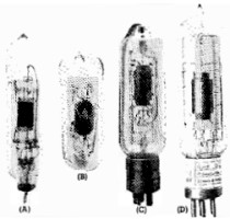
Fig. 243 - Development of the space charge grid vacuum tube.
Reproduced from "Veroffentlichungen aus dem Gebiete der Nachrichtentechnik"1935.
Triode tubes were also made during this period by other German manufacturers,
among them Huth,316 Seddig.317 and Auer.318 Some of these
tubes are shown in Figs. 238 and 239. It will be observed that the Huth tube shown
was of plane parallel electrode construction. Earlier Huth tubes used a cylindrical
element assembly but Huth was compelled to change to the plane electrodes because
of patent difficulties, The earlier Huth tubes bore RE numbers similar to those
of Telefunken, but those with plane electrode systems were designated by LE numbers.319
It is during this period also that we find considerable research effort being expended
in Germany on the multiple electrode tube. It was early realized by Dr. Walter Schottky320
of the Siemens & Halske Company that there were limits to the amplification
which could be attained by the use of a triode and he set out to devise a tube which
would be capable of high amplification with the low anode potentials available in
Army field equipment.
Accordingly he investigated the possibility of modifying the high vacuum triode
by the insertion of additional electrodes. He patented the space charge principle
in 1915321 and the "protective network" type in 1916.322 His
first patent on a multiple electrode tube was German patent D.R.P. 300617, issued
June 1, 1916, and covered a tube designated by Schottky as a "protective network"
(Schutznetz) type. Another patent, D.R.P. 300192 issued June 21, 1916, covered another
double grid arrangement. Patent D.R.P. 300191 for a tube having a space charge grid
in which both grids were characterized by being composed of strips of sheet metal
placed with edges toward the cathode was issued on January 24, 1917.
The first production of the multiple electrode Schottky tubes were tetrodes of
the protective network type, known as the SSI, SSII, and SSIII. While the protective
network was a grid inserted between the control grid and the anode these tubes differed
from the modern "screen grid" type in that no attempt was made to use the additional
grid to minimize the electrostatic capacitance between the anode and the control
grid. This difference is relatively unimportant for low frequency work, but is of
great importance in high frequency applications. As Schottky himself pointed out,
his tubes were not suitable for use at high frequencies.323
The early model and later quantity production type of the SS tubes are shown
in Fig. 241. Fig. 241 (left) shows the earliest construction of this type. The electrode
assembly was cylindrical, the grids were of the "squirrel cage" type, and a double
press was used. The electrodes were slotted so that it was possible to insert the
filament assembly into the electrode assembly after fabricating the two separately.
Fig. 241 (right) shows a single-ended production type tube with glass "star" as
the support of the electrode system.
The SSI was first manufactured in 1917. It had a filament which operated with
0.4 ampere at 2.4 volts. The anode potential was 35 volts and the potential of the
protective network was 15 volts. When so operated it gave an amplification of about
50 and had a mutual conductance of 250 micromhos.
The SSII, also known as the RE97,324 was a lower powered, lower gain
tube, operating with a filament current of 0.24 ampere at 1.9 to 2.2 volts, and
with 10.5 volts on both the anode and the protective network. It had an amplification
factor of 30 and mutual conductance of 30 micromhos. The SSIII, also known as the
RE114, drew a filament current of 0.55 ampere at 3.2 volts and operated with 120
volts on the anode and 45 volts on the protective network. It had an amplification
factor of about 100 and a mutual conductance of 250 micromhos. The internal resistance
was about 250,000 ohms.
Tubes of the space-charge grid type were also manufactured during this period.
Typical examples of the smaller ones are the Telefunken RE20 and RE26, shown in
Fig. 242. Both these tubes had tungsten filaments operating at 0.5 ampere at 2.8
and 4.0 volts respectively. They operated at 12 to 18 volts on the anode and space
charge grid, had an amplification factor of about 8 and mutual conductance of about
350. Since they had 5 prong bases they required special sockets.
Larger tubes of the space-charge grid type were also developed and Fig. 243 shows
the development series of one such tube. Figs. 243(A) and 243(B) show the early
models. The grids are of wire netting. The space charge grid is small in diameter
while the control grid is very close to the anode. Fig. 243(C) shows a production
type tube of the vintage of 1919, still with the double press, Fig. 243(D) illustrates
the final construction which was put into production about 1920.
Combination space charge and protective network tubes with three grids were also
developed and some of these are shown in Fig. 245. The tube at the left is an experimental
type with three grids using a double press and slotted electrodes. That at the right
is a production type similar to the SS series.
In parallel with the work on receiving tubes Telefunken and the other German
concerns had also been carrying on the development of transmitting tubes. The first
of these to be made in quantities was the RS1, shown in Fig. 235. It gave about
three watts output when operated with 400 volts on the anode, in the apparatus in
which it was first used, an Army trench transmitter. It was capable of operation
at higher anode voltages, and at 600 to 800 volts would put out 10 to 20 watts.325
The RS2 and RS3 were of no particular importance. The RS4 was a higher powered tube
giving 50 to 75 watts output at 1000 to 2000 volts on the anode, and had a filament
which took 3 amperes at 9 volts. The RS5, shown in Fig. 236, was an RS4 with improved
characteristics. It took a filament current of 3 amperes at about 8 volts. The successor
to the RS4 was the RS17, the evolution of which is shown graphically in Fig. 240.
All these transmitting tubes were characterized by the excellent glass work shown
in their internal construction. This construction was common to all of the small
transmitter tubes of early German manufacture, and is again exemplified in the TKD
ST12 shown in Fig. 237.326 This tube again shows the effect of metal shortages.
The interior portion of the base, in which the connecting pins are mounted, is of
wood and the shell is of iron, with a poor nickel plate.
This series of articles has been presented to trace the development which took
place up to the end of World War I along a particular branch of the network of roads
which led to the modern radio tube. It has attempted to trace the evolution from
studies of the interactions between heat and electricity as pursued by the early
philosophers and by the physicists who followed them. These limitations have been
adopted in an attempt to report the work done in the years where there is a dearth
of readily available published material.
In any field of human activity books and periodicals are published by and for
those interested. Such was the case in the early days of radio, with which the vacuum
tube is so inextricably bound up. Much of the widespread interest in radio in the
United States may be traced to the band of eager enthusiasts who made up the amateur
fraternity in the days before World War I. The ham of those days spent his spare,
and often not-so-spare, cash, burned his midnight electricity, and experimented
unceasingly to fathom the mysteries of transmission and reception. Much progress
came from interchange of ideas and experiences with others of like inclination.
But unlike the situation existing today the facilities for such interchange were
very limited. Books and periodicals dealing with such matters were few and far between.
Periodicals in particular were of limited circulation, aimed at the experimenter
of high school age and pocketbook and, except in a few cases, were not deemed of
sufficient importance to be included in the permanent files of public libraries.
Few books were written, since the men who were doing the work were too busy doing
it to write about it.

Fig. 244 - RE16 vacuum tube. The top is painted red. Reproduced
from Nesper's "Der Radio Amateur"1924.

Fig. 245 - Development of the Schottky three grid vacuum tube.
Reproduced from "Veroientlichungen aus dem Gebiete der Nachrichtentechnik" 1935.
With the advent of broadcasting and the great increase in adult popular interest
in radio there came into being a number of widely circulated periodicals, technical
and popular, both here and abroad, which published large quantities of information
on current radio and vacuum tube development. These were preserved in most libraries
of any size and are usually available to the earnest student of vacuum tube history.
For this reason little space has been devoted to cold cathode, cathode ray, multigrid,
and higher powered transmitting tubes, such as the silica envelope type made by
Philips-Mullard, the water-cooled copper-to-glass seal type developed by Housekeeper,
and the larger radiation cooled types. Information on these phases of development
can be obtained from these sources by the student or collector who seeks information
on a specific type, and its collation and republication here is considered unjustified.
References
312. Martin-"Telefunken Rohrentypen" Telefunken Zeitung, Vol. 4, No. 32/33, September
1923, pp. 5155.
313. Rukop, Hans"25 Jahre TelefunkenDie Teleftistkenrohren und ihre Geschichte"
Telefunken Festschrift1928, p. 49.
314. Banneitz, F. "Taschenbuch d e r drahtlosen Telegraphie und Telephone" SpringerBerlin1927,
p. 476.
315. Harper, A. E.`Amplifying Bulbs" QST, Vol. 4, No. 7, February 1921, pp. 2728.
316. Dr. Erich F. Ilnlh Gesellschaft fur Funk entelerlruphie.
317. (R.I.W.) Smithy, Wurzbnr.q.
318. Auer Studiengesellschaft fur elektrische Leuchtrohren.
319. Groskowski, J.'Qes launpes a plusieurs electrodes et leurs applications
en radiotechnique" Etienne ChironParis1925, p. 125.
320. Schottky. W.' fiber Hochvakuum Verstärker III Teil Mehrgitterrohren" Archiv
fur Elektrotechnik. Vol. 8, No. 9, December S. 1919, pp. 299328.
321. D.R.P. 310605, issued March 19, 1915.
322. D.R.P. 87745, issued May 31, 1916.
323. See reference 323, p. 320.
324. Polilalunn, R. und Gehrts .4."Werdegan,q einer Verstarkerrohre" Elektrische
NacJarie1ilcitTeehnik, Vol. 2, No. 3, Illoreb 1925, pp. 6574.
325. See reference 316, p. 142.
326. "TED" is the trade mark of Suddeutsche Telefon, Apparate-, Kabel, und DrahtWerke,
Nurnberg.
 If you, like me, appreciate the sheer engineering
genius and artistry of a vacuum tube - especially the special purpose types - then
you'll want to peruse the extensive collection of Mr. Robert Gillespie. His
vacuum
tube gallery is hosted on the RadioMuseum.org website. He writes: "I started
collecting tubes when I was 10, they were like little pieces of artwork. My fascination
with tubes took off when I found my first industrial tube in an old warehouse. I
do enjoy the odd photocells and photomultipliers, anything built by hand and not
by machine. Currently, my focus is on collecting anything pre-1925 from anywhere
in the world - which has been greatly boosted as I am now the curator of the Gerald
Tyne Collection, author of 'Saga of the Vacuum Tube,' 1977." If you have a unique
vacuum tube not already represented there, you are welcome to submit photos and
information. There are 1,629 as of this writing. If you, like me, appreciate the sheer engineering
genius and artistry of a vacuum tube - especially the special purpose types - then
you'll want to peruse the extensive collection of Mr. Robert Gillespie. His
vacuum
tube gallery is hosted on the RadioMuseum.org website. He writes: "I started
collecting tubes when I was 10, they were like little pieces of artwork. My fascination
with tubes took off when I found my first industrial tube in an old warehouse. I
do enjoy the odd photocells and photomultipliers, anything built by hand and not
by machine. Currently, my focus is on collecting anything pre-1925 from anywhere
in the world - which has been greatly boosted as I am now the curator of the Gerald
Tyne Collection, author of 'Saga of the Vacuum Tube,' 1977." If you have a unique
vacuum tube not already represented there, you are welcome to submit photos and
information. There are 1,629 as of this writing.
Note: the entire series of "The Saga of Vacuum Tubes" articles
can be accessed on the American Radio History website in PDF format. Below, I have
take taken the time to list and link to each edition containing parts 1 through
22, along with the pages on which they begin.
-
Part 1 of this especially-prepared series of articles giving the complete history
and development of the radio vacuum tube. March 1943, p25.
-
Part 2 of this authoritative series, shows the tremendous amount of preliminary
work that led to the discoveries of the radio tube. April 1943, p31.
-
Part 3 of this series covering the Edison era, illustrating many of his outstanding
inventions and the problems encountered. May 1943, p26.
-
Part 4 covering the development of communications for wireless telegraph, using
thermionic tubes for the first time. July 1943, p30.
-
Part 5 of the era of controversy between patent rights on thermionic tubes designed
by de Forest, Fleming, Weagant and others. August 1943, p26.
-
Part 6 Covering the period daring which Dr. Lee de Forest urns at the height
of his inventive career. Many of his tube patents are discussed. September 1943,
p26.
-
Part 7 of the series, covering the period during which the first commercial
grid-type Audion tube was manufactured for civilian use. October 1943, p26.
-
Part 8 Covering the period during which the elements of the triode tube were
redesigned to obtain increased performance. November 1943, p26.
-
Part 9 The early constructional problems of the the Western Electric type-101
vacuum tube - covering its multiplicity of shapes and sizes. January 1944, p38.
-
Part 10 Covering the evolution of the vacuum tube through the years 1914 to
1918, as a result of the research work done by Western Electric. March 1944, p50.
-
Part 11 Covering a number of the unusual earlier constructed tubes that are
of particular interest to many old timers. April 1944, p54.
-
Part 12 The period of increased activity in the wireless industry with Lee de
Forest's development of suitable oscillator and detector tubes. June 1944, p52.
- Part 13 Covering
the developments by the General Electric Co. of higher power output alternators
for use in the fields of telegraphy and telephony. September 1944, p46.
- Part 14 Covering
the development of the "Kenotron," "Pliotron," "Dynatron," and "Magnetron" by Drs.
Langsnuir, Dushman, and Hull of the General Electric Laboratories, during the years
1913 to 1921. November 1944, p56.
-
Part 15 The early growth of the amateur fraternity, with the development and
manufacture for public use of the Audion and crystal detector. January 1945, p54
(go to PDF p104 due to "Engineering Department" insert).
-
Part 16 The early manufacture and sale of the "Electron Relay" and other amateur
tubes by Otis R. Moorhead. March 1945, p52.
-
Part 17 A study of repeater tube developments in local and long-distance telephonic
transmissions. May 1945, p58.
-
Part 18 Continuing our study of telephone repeater-tube developments in this
country and abroad and their application during the first World War. July 1945,
p56.
-
Part 19 Covering developments and applications of tubes in England from 1911
through World War 1. September 1945, p54.
-
Part 20 Continuing the study of the evolution of the vacuum tube and the many
mechanical problems that were confronted in their manufacture during World War 1.
November 1945, p51.
- Part 21 Vacuum tube
developments that were carried on in France and Germany during the first World War.
February 1946, p54.
- Part 22, Concluding
article of a historical series which has covered the development of the vacuum tube
from its conception to the end of World War 1. April 1946, p52.
Posted May 20, 2020
|