|
This is Part 13 of a series
entitled "The Saga of the Vacuum Tube," by Gerald Tyne, that appeared in Radio
News magazine in 1944. Part 1 was printed in March 1943, and Part 22,
the final chapter, was published in April 1946. It could have been a stand-alone
book. If I manage to be able to buy issues with some of the other parts, those will
be posted as well. You might be aware of the origins of the amplifying vacuum tubes,
beginning with the accomplishments of Dr. de Forest and his Audion. As with
most new technologies, progress moved very rapidly once other researchers glommed
on to the concept. Here, Mr. Tyne discusses the development of the "Kenotron,"
"Pliotron," "Dynatron," and "Magnetron," by Drs. Langmuir, Dushman and Hull
of the General Electric Laboratories, during the years 1913 to 1921.
See list of all 22 parts at bottom of page.
The Saga of the Vacuum Tube - Part 13
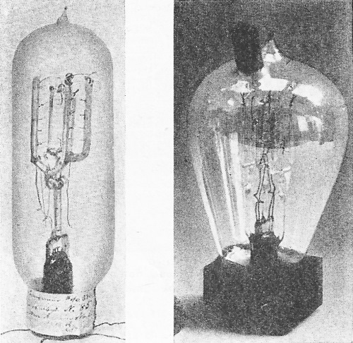
Fig. 149 - Langmuir's "Tungsten Wire Audion No. 2". Reproduced
from Interference Record, Interference No, 40,380.
Fig. 150 - Early type of wire element Pliotron, now in Science
Museum, South Kensington, England. Photograph copyright by H. M. Stationery Office.

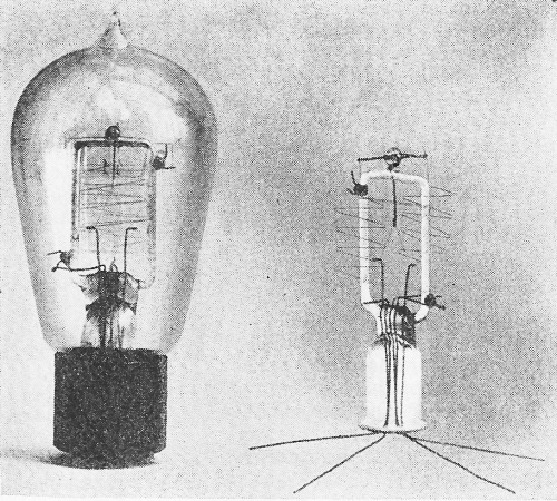
Fig. 151 - Early Langmuir Pliotron complete (left). Element assembly
on stem (right). Photograph courtesy General Electric Company.
By Gerald F. J. Tyne
Research Engineer, N. Y.
Part 13. Covering the developments by the General Electric Co. of higher power-output
alternators for use in the fields of telegraphy and telephony.·
The development of the comparatively crude Audion into a satisfactory high-vacuum
telephone repeater element was undertaken and carried through by the engineers of
the Western Electric Company because of an urgent need. The problems of wire telephony
in general do not involve the use and control of large powers, and the Audion, as
submitted for their consideration by de Forest, was limited to low power applications.
The General Electric Company, on the other hand, dealt essentially in comparatively
high-power devices. Why then did they become interested in the low-power Audion?
Paradoxically enough it was because they had need of a high-power device-but one
with the type of characteristics exhibited by the Audion at low power levels.
Although in the popular mind the name of the General Electric Company is associated
with power equipment in the early 1900's, the engineers of this Company had for
some years been engaged in an attempt to develop a radio-frequency alternator for
long-distance communication. The work was begun about 1904 at the request of Mr.
Reginald A. Fessenden of the National Electric Signaling Company. At that time Fessenden
was working at Brant Rock, Massachusetts, trying to develop a method of obtaining
a continuous flow of high-frequency energy, and had requested the General Electric
Company to undertake the development of an alternator to operate at 100,000 cycles.
He was familiar with the work done previously at the General Electric laboratory
by Thompson and Steinmetz along this line. Fessenden was using an arc transmitter,
the only satisfactory generator of continuous waves of that day. He experienced
many difficulties in this work because the arc was tricky to handle and not entirely
free from self-modulation. When Fessenden appealed to the General Electric Company
to undertake this work, E. F. W. Alexanderson was assigned the job of developing
such an alternator. The result of the next few years' work on his part was what
became known as the Alexanderson Alternator. The real significance of this development
was realized in 1919 when the General Electric Company, after having spent millions
of dollars to make such a device practicable, refused to sell to its only customer,
the British-controlled Marconi Company, and in so doing helped return the control
of transatlantic radiotelegraph stations to the United States.186 By
this act also, the General Electric Company paved the way for the founding of the
Radio Corporation of America.
Therefore, it might be said that in the early 1900's the General Electric Company
was trying to build a machine - a mechanical device - to do the job of the vacuum-tube
transmitter of the present day.
By 1913 Alexanderson had been able to construct satisfactory alternators of several
kilowatts output at frequencies up to 200,000 cycles.187,188 They were
satisfactory, that is, for use in continuous-wave telegraphy, but could not be used
for satisfactory radiotelephonic communication since no method of adequate modulation
of their output was available. Alexanderson had tried various methods of modulation
with varying degrees of success. One method utilized a generator with its field
excited by the telephone current. Another involved the use of the so-called "magnetic
amplifier" or magnetic modulator.189 A third was the use of a three-electrode
mercury arc tube, in which an attempt was made to control the arc current by the
use of the third electrode. None of these methods was completely satisfactory, and
Alexanderson continued his search for a better modulator.
In 1912 the General Electric Company sold to John Hays Hammond, Jr., two high-frequency
alternators for use in his experimental work on radio-controlled devices. In October
of that year Alexanderson discussed with Hammond, at the latter's laboratory in
Gloucester, Mass., the problem of obtaining the necessary modulation. While there,
Alexanderson was told of some receiving apparatus, designed and constructed by Benjamin
F. Miessner, one of Hammond's assistants, in which Audions were used. Alexanderson,
who had never seen an Audion, felt from the description of the Audion and its characteristics
that it might be promising as a high-frequency relay. He thought that it was in
many ways defective but considered that the defects might be overcome. He therefore
arranged to obtain a sample of the Audion from Hammond, to see if it might be made
into a suitable device for the application he had in mind.
At Schenectady he showed the Audion to Drs. W. D. Coolidge and Irving Langmuir,
with whom he often discussed problems. The discussion with Langmuir was fruitful.
Langmuir said that he could develop a high-vacuum device of the three-electrode
type which would function satisfactorily as a high-frequency relay. Alexanderson
felt that such a device as Langmuir described could be used not only for modulation
of the transmitted wave from his alternator, but also could be used in a new system
of reception on which he was working. Accordingly, Langmuir set about the development.
Irving Langmuir had been in the employ of the General Electric Company since
1909. He was graduated from Columbia University in 1903, and had done postgraduate
work at the University of Göttingen under Nernst, receiving his Ph.D. in 1906.
When he entered the employ of the General Electric Company he attacked some of the
problems still to be solved in connection with the tungsten filament incandescent
lamp. The Coolidge process of making drawn tungsten wire had recently been introduced
into commercial manufacture and had given rise to a number of problems, as does
any new process.
One of the problems which Langmuir studied in connection with tungsten filament
lamps was the blackening of the bulbs in service. This same problem in connection
with carbon filament lamps, it will be remembered, led to the discovery by Edison
of the "Edison Effect." It was the common idea in the General Electric laboratory
that this blackening, in the case of the tungsten filament lamp, was due to secondary
causes, among them electric discharges. It had been observed that the "blue glow,"
characteristic of insufficiently exhausted lamps, caused very rapid blackening.
Also the presence of water vapor in the lamp bulb accelerated the blackening. From
this it would seem that better vacuums were desirable .
Others had attempted to solve the problem by increasing the vacuum. Langmuir
adopted a different approach. He attempted to determine the cause of the blackening
by increasing the amount of the impurities introduced into the bulb. Particularly
he studied the effect on the filament of gases introduced. Some of these, such as
hydrogen, would disappear if introduced in limited amounts. Others, such as nitrogen,
would react with the tungsten vapor given off by the hot filament.
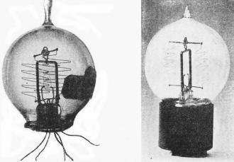
Fig. 152 - Early Langmuir Pliotron, before exhaust. This Pliotrom
has a grid of tungsten wire 0.4 mil in diameter, wound on a metal frame, with a
pitch of 120 turns per inch. The anode is of 7 mil tungsten wire. Note the 5 leads,
two filament, one grid, and both ends of wire anode. Exact date uncertain, but prior
to 1917.
Fig. 153 - Completed, based Pliotron, Type CA. Vintage of 1917.
This is a high-mu triode. The filament takes 1.0 ampere at 3.5 volts. The usual
plate voltage was 180 volts. Photograph courtesy General Electric Company.
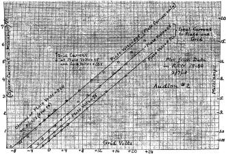
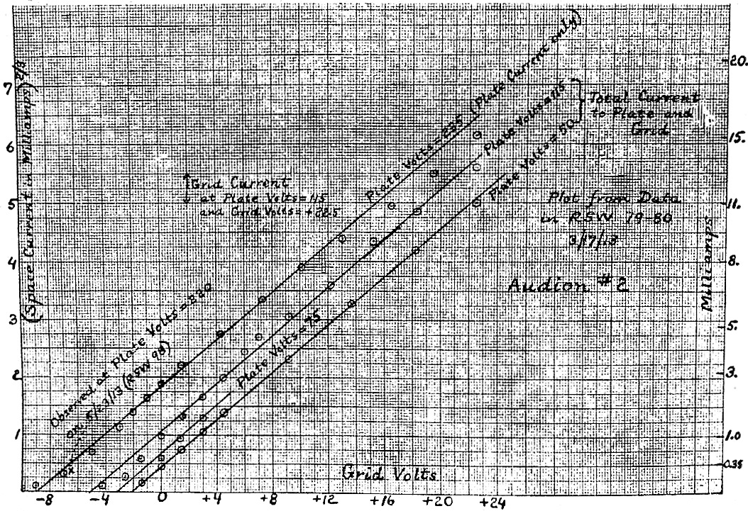
Fig. 154 - Characteristic curve of Langmuir "Tungsten Wire Audion
No. 2". Reproduced from Transcript of Record, General Electric Company vs. De Forest
Radio Company, U.S.C.C. of A., Nos. 3799, 3800, 3801, March Term, 1928.
In this work Langmuir had to differentiate between the effects due to evaporation
of the filament - because of its high operating temperature - and the effects due
to electric discharges within the bulb. To accomplish this he used low-voltage filaments
to study the evaporation phenomena, and high-voltage (50-250 volt) filaments to
study the effect of discharges. From all this he began to get a picture of what
would happen in a perfect vacuum. He concluded that the blackening of the bulb was
due to normal evaporation of the filament, not to electric discharges. He found
the reason why the presence of water vapor accelerated the blackening. He found
that even if the vacuum were perfect the blackening still would occur.
From his studies he concluded that the presence of pure gases was not harmful,
and from this work came the high-efficiency, gas-filled incandescent lamp.
During the period just before Alexanderson brought the Audion to his attention,
Langmuir had been studying the properties of filaments as a function of their length.
It was thought at the time that with long filaments, requiring a comparatively high
voltage for their operation, there might be a considerable amount of current flowing
through the vacuous space and hence, for the same total current into the lamp, the
actual filament current might be less and the lamp less efficient. Langmuir looked
for this effect but could not find it. That is, in well-exhausted lamps there was
a negligible space current, regardless of the length at the filament. Others had
worked along this same line and were of the opinion that in a perfect vacuum there
would be no space current.
One of these others was Dr. Coolidge, who was working on X-ray tubes. In the
old-fashioned X-ray tube of high power most of the electrical energy supplied to
the tube appeared at the anode, which would operate sometimes at white heat. Coolidge
used tungsten for the anode and in some cases tried tubes with tungsten cathodes
as well. In the case of the tungsten cathodes he found that after the tube had been
in operation for some time the cathode also became white hot, and shortly thereafter
the tube ceased to pass current and became inoperative. Coolidge was aware of the
"clean-up" effect of white-hot tungsten and believed that the stoppage of the tube
was caused by its becoming too "hard," that is, the vacuum had become too high to
permit the passage of current. Langmuir's own experimental work indicated that these
currents would become very small when the highest vacuums, obtained by thoroughly
baking the lamps to free them from occluded gases, were attained.
On the other hand, Langmuir was familiar with the work of O. W. Richardson on
thermionic emission, which showed that thermionic emission increased with temperature.190
Calculations based on Richardson's equations indicated that at the temperature at
which Langmuir was operating his tungsten filaments the thermionic currents should
have been hundreds of amperes per square centimeter of filament surface. He checked
the discharge from a hot filament to a cold anode in the presence of mercury vapor
and found that the space current followed Richardson's law up to very high filament
temperatures. Hence, he concluded that there was nothing abnormal about tungsten
and that the filaments actually were emitting electrons in accordance with Richardson's
law.
The ordinary tungsten lamp of that time had a long zigzag filament of six loops,
with two leads brought out and connected to a base for use in a standard screw type
socket. Langmuir had made some experimental lamps in which two additional leads,
connected to intermediate points on the filament, were brought out. These leads
were placed so that between any two consecutive leads there were two loops of filament.
These lamps were exhausted by the ordinary procedure, but Langmuir then proceeded
to raise the middle two loops of the filament to' a very high temperature and vaporize
the tungsten, so as to "clean-up" the vacuum. The act of vaporizing the tungsten
assists in the removal of some of the residual gases. The tungsten vapors will combine
with nitrogen, oxygen, carbon monoxide, and carbon dioxide, and these are the gases
which are likely to be present in the bulbs. When this was done, and the middle
portion of the filament burnt out, there were left two sections of filament electrically
separated from each other, between which a voltage could be applied.
Langmuir then heated one filament by passing a current through it, and applied
a voltage between that filament and the other which was cold. He measured the space
current as a function of temperature for various filament temperatures and compared
the results obtained with values calculated according to Richardson's law. He found
that at first the space current followed the law, but as the temperature increased
the space current tended toward a constant value. This always occurred, although
the limiting value was different for different voltages between the hot and cold
electrodes. He found that this limiting current was approximately proportional to
the voltage difference between the hot and cold electrodes, and to the area of the
anode.
He discovered also that a potential applied to the bulb externally affected the
space current. If, for example, he placed one hand on the bulb and with the other
hand touched the terminals of the d.c. power circuit in the laboratory, the space
current increased or decreased.
By November 22, 1912, Langmuir had accumulated enough data to enable him to formulate
a qualitative theory concerning the space current. This theory, as entered in one
of his notebooks under that date, was as follows:
"New Theory of Edison Current. The velocity of electrons in a conductor corresponds
to that produced by a fall through a potential diff. (sic) of only a few tenths
of a volt. Electrons leaving a filament will leave irrespective of the presence
of a field, but they will only travel a very short distance if there is an electric
field of only 0.1 volt per centimeter against them. Hence, around filament there
is an atmosphere of electrons in equilibrium with the filament. Below a certain
temperature the potential is determined by wires (i.e, electrodes) only.
"Above a certain temperature the concentration of electrons becomes so great
that they determine the field. Hence, two laws: Richardson's at low and some other
at high temperature.
"Cooling bulb has no effect when no gas molecules present, but if gas is there
the molecules collide with electrons (which have the same velocities as those of
the filament) and slow them up and make them more readily absorbed by the anode
wires."
This last paragraph was an attempt to explain the fact that the presence of gas
caused an increase in the space current. This, we know now, was not the correct
theory. The increase in current when the gas is present at high voltage is due to
the fact that the positive ions formed, neutralize the space charge and allow the
space current to rise toward the temperature saturation value.
These experiments threw an entirely new light on the theory of discharges from
hot electrodes in very-high vacuums. It showed why, in the past, such small space
currents were found under conditions where large currents were indicated by Richardson's
equation.
Langmuir attached great importance to this explanation and theory, and proceeded
to make a detailed study of the laws governing the phenomenon under high-vacuum
conditions. His first step was to have constructed another lamp in which were placed
two independent filaments, both of which could be heated during the process of exhausting
the bulb. The bulb of this lamp was baked at high temperature during exhaust and
a liquid air trap was used to remove traces of water vapor and carbon dioxide. Thus
Langmuir removed as much of the occluded gases as possible, and pushed the vacuum
to the limit attainable with the available equipment.
Tests run on this new bulb were made using anode voltages up to 250 volts d.c.
and about 500 volts a.c. When the test data was plotted in a curve, the shape of
the curve indicated that the space current varied as the 1.5 power of the voltage.
This, then, was the background of knowledge born of experience that enabled Langmuir
to tell Alexanderson, in January of 1913, that he could improve the gadget which
Alexanderson had obtained from Hammond, and make of it a device which would enable
Alexanderson to do what he wanted. In order to do so Langmuir needed another assistant,
and William C. White was assigned to this work. White studied the characteristics
of the Audion and discussed the results of his tests with Langmuir.
While White was studying the Audion, Langmuir had made up a tube similar to the
Audion but with leads widely separated in order to enable him to apply high voltages
during the exhausting process, and thus heat the electrodes by bombardment and free
them from occluded gases. The results obtained were unsatisfactory and Langmuir
decided to alter the construction of the tube in such a way as to facilitate the
evacuation.
In order to accomplish this he abandoned the conventional Audion construction
and made a three-electrode tube in which all three of the electrodes (filament,
grid, and anode) were made of wire. The filament was made of 2.7 mil tungsten wire
and was about 5 1/2 inches in length. The grid was of 1.5 mil wire, hand wound on
a glass frame. The anode was a zigzag wire 5 mils in diameter. The filament operated
at about 2.5 amperes. This tube was known as "Tungsten Wire Audion No. 2" and is
shown in Fig. 149.
This type of construction was adopted so that the electrodes could be heated
by current from an external source during exhaust, in order to expel the occluded
gases. This form of construction was used from March, 1913 until well into 1914
for all small tubes for operation at or below 250 volts, and somewhat longer for
special tubes. Samples of tubes using this construction are shown in Figs. 150,
151, 152, and 153.
After this tube had been exhausted and sealed off the pump at a pressure of 0.05
micron it was subjected to numerous tests. In one case the anode voltage was held
constant at 250 volts and the anode current measured as a function of grid voltage.
Curves plotted of total space current showed that the space current obeyed the 3/2
power law. These curves are reproduced in Fig. 154.
This tube was also tested and functioned satisfactorily as a detector of wireless
signals. Others made up shortly thereafter were also operated successfully when
tested, in May of 1913, by Alexanderson for use as radio-frequency amplifiers.
While these experiments were under way, Coolidge was continuing his work on X-ray
tubes. In December, 1912, Langmuir had discussed with Coolidge the results of his
experiments and suggested that Coolidge try a tungsten cathode which could be heated
by electric current from an external source, for the purpose of getting electrons
in his X-ray tube. He told Coolidge that electrons were emitted from such filaments
even in the highest vacuum, and that controlling the heating current would control
the electron emission and the space current, independently of the applied voltage.
Coolidge immediately proceeded to build an X-ray tube using an independently heated
tungsten cathode of the type suggested. He used a tungsten anode, which he degassed
by electron bombardment while the tube was still on the pump. He found it necessary
to add a focusing shield around the cathode, and with this addition obtained a tube
which was steady in operation, with none of the crankiness of the old type of cold-cathode
tube, and one with which he could obtain reproducible results. By December, 1913,
Coolidge had developed this tube to the point of commercial use, and described it
in a paper before the American Physical Society.191
References
186. Report of the Federal Trade Commission on the Radio Industry. Government
Printing Office - 1924; pp. 14-16.
187. Alexanderson, E. F. W. Alternator for 100,000 Cycles." Trans. A.I.E.E.,
Vol. 28, Part 2, 1909, pp. 399-415.
188. Alexanderson, E. F. W. Maqnetic Properties of Iron at Freqqencies Up To
200,000 Cycles." Trans. A.I.E.E., Vol. 30. Part 3, 1911, pp. 2433-2454.
189. Alexanderson, E. F. W. amd Nixhoft. S.P. - A Magnetic Amplifier for Radio
Telephone." Proc. I.R.E., Vol. 4, 1916, pp. 101- 129.
190. Richardson, Owen Williams - See Proceedings of Cambridge Philosophical Society,
Vol. 11, page 296 for preliminary note on this work.
Richardson, Owen Williams "The Electrical Conductivity Imparted to a Vacuum by
Hot Conductors." Philosophical Transactions of Royal Society of London, A, Vol.
201, 1903, pp. 497-549. An abstract of this paper will be found in Proc. Roy. Soc.
Londn, Vol. 71, 1903, pp. 415-418.
Richardson, O. W. and Brown, F. C. - "The Kinetic Energy of the Negative Electrons
Emitted by Hot Bodies." Philosophical Magazine, 6th Series, Vol. 16, No. 93, September
1908, pp. 353-376.
Richardson, Owen Williams - "Thermionics Phil. Mag., 6th Series, Vol. 17, No.
102, 1909, pp. 813-833.
191. Coolidge, W. D. - A Powerful Roentgen Ray Tube with a Pure Electron Discharge."
Physical Review, 2nd Series, Vol. ·2, No. 6, December 1913, pp. 409-430.
Captions for Illustrations
Fig. 149. Langmuir's "Tungsten Wire Audion No. 2". Reproduced from Interference
Record, Interference No, 40,380.
Fig. 150. Early type of wire element Pliotron, now in Science Museum, South Kensington,
England. Photograph copyright by H. M. Stationery Office.
Fig. 151. Left - early Langmuir Pliotron complete. Right - element assembly on
stem. Photograph courtesy General Electric Company.
Fig. 152. Early Langmuir Pliotron, before exhaust. This Pliotrom has a grid of
tungsten wire 0.4 mil in diameter, wound on a metal frame, with a pitch of 120 turns
per inch. The anode is of 7 mil tungsten wire. Note the 5 leads, two filament, one
grid, and both ends of wire anode. Exact date uncertain, but prior to 1917.
Fig. 153. Completed, based Pliotron, Type CA. Vintage of 1917. This is a high-mu
triode. The filament takes 1.0 ampere at 3.5 volts. The usual plate voltage was
180 volts. Photograph courtesy General Electric Company.
Fig. 154. Characteristic curve of Langmuir "Tungsten Wire Audion No. 2". Reproduced
from Transcript of Record, General Electric Company vs. De Forest Radio Company,
U.S.C.C. of A., Nos. 3799, 3800, 3801, March Term, 1928.
(To be continued)
 If you, like me, appreciate the sheer engineering
genius and artistry of a vacuum tube - especially the special purpose types - then
you'll want to peruse the extensive collection of Mr. Robert Gillespie. His
vacuum
tube gallery is hosted on the RadioMuseum.org website. He writes: "I started
collecting tubes when I was 10, they were like little pieces of artwork. My fascination
with tubes took off when I found my first industrial tube in an old warehouse. I
do enjoy the odd photocells and photomultipliers, anything built by hand and not
by machine. Currently, my focus is on collecting anything pre-1925 from anywhere
in the world - which has been greatly boosted as I am now the curator of the Gerald
Tyne Collection, author of 'Saga of the Vacuum Tube,' 1977." If you have a unique
vacuum tube not already represented there, you are welcome to submit photos and
information. There are 1,629 as of this writing. If you, like me, appreciate the sheer engineering
genius and artistry of a vacuum tube - especially the special purpose types - then
you'll want to peruse the extensive collection of Mr. Robert Gillespie. His
vacuum
tube gallery is hosted on the RadioMuseum.org website. He writes: "I started
collecting tubes when I was 10, they were like little pieces of artwork. My fascination
with tubes took off when I found my first industrial tube in an old warehouse. I
do enjoy the odd photocells and photomultipliers, anything built by hand and not
by machine. Currently, my focus is on collecting anything pre-1925 from anywhere
in the world - which has been greatly boosted as I am now the curator of the Gerald
Tyne Collection, author of 'Saga of the Vacuum Tube,' 1977." If you have a unique
vacuum tube not already represented there, you are welcome to submit photos and
information. There are 1,629 as of this writing.
Note: the entire series of "The Saga of Vacuum Tubes" articles
can be accessed on the American Radio History website in PDF format. Below, I have
take taken the time to list and link to each edition containing parts 1 through
22, along with the pages on which they begin.
-
Part 1 of this especially-prepared series of articles giving the complete history
and development of the radio vacuum tube. March 1943, p25.
-
Part 2 of this authoritative series, shows the tremendous amount of preliminary
work that led to the discoveries of the radio tube. April 1943, p31.
-
Part 3 of this series covering the Edison era, illustrating many of his outstanding
inventions and the problems encountered. May 1943, p26.
-
Part 4 covering the development of communications for wireless telegraph, using
thermionic tubes for the first time. July 1943, p30.
-
Part 5 of the era of controversy between patent rights on thermionic tubes designed
by de Forest, Fleming, Weagant and others. August 1943, p26.
-
Part 6 Covering the period daring which Dr. Lee de Forest urns at the height
of his inventive career. Many of his tube patents are discussed. September 1943,
p26.
-
Part 7 of the series, covering the period during which the first commercial
grid-type Audion tube was manufactured for civilian use. October 1943, p26.
-
Part 8 Covering the period during which the elements of the triode tube were
redesigned to obtain increased performance. November 1943, p26.
-
Part 9 The early constructional problems of the the Western Electric type-101
vacuum tube - covering its multiplicity of shapes and sizes. January 1944, p38.
-
Part 10 Covering the evolution of the vacuum tube through the years 1914 to
1918, as a result of the research work done by Western Electric. March 1944, p50.
-
Part 11 Covering a number of the unusual earlier constructed tubes that are
of particular interest to many old timers. April 1944, p54.
-
Part 12 The period of increased activity in the wireless industry with Lee de
Forest's development of suitable oscillator and detector tubes. June 1944, p52.
- Part 13 Covering
the developments by the General Electric Co. of higher power output alternators
for use in the fields of telegraphy and telephony. September 1944, p46.
- Part 14 Covering
the development of the "Kenotron," "Pliotron," "Dynatron," and "Magnetron" by Drs.
Langsnuir, Dushman, and Hull of the General Electric Laboratories, during the years
1913 to 1921. November 1944, p56.
-
Part 15 The early growth of the amateur fraternity, with the development and
manufacture for public use of the Audion and crystal detector. January 1945, p54
(go to PDF p104 due to "Engineering Department" insert).
-
Part 16 The early manufacture and sale of the "Electron Relay" and other amateur
tubes by Otis R. Moorhead. March 1945, p52.
-
Part 17 A study of repeater tube developments in local and long-distance telephonic
transmissions. May 1945, p58.
-
Part 18 Continuing our study of telephone repeater-tube developments in this
country and abroad and their application during the first World War. July 1945,
p56.
-
Part 19 Covering developments and applications of tubes in England from 1911
through World War 1. September 1945, p54.
-
Part 20 Continuing the study of the evolution of the vacuum tube and the many
mechanical problems that were confronted in their manufacture during World War 1.
November 1945, p51.
- Part 21 Vacuum tube
developments that were carried on in France and Germany during the first World War.
February 1946, p54.
- Part 22, Concluding
article of a historical series which has covered the development of the vacuum tube
from its conception to the end of World War 1. April 1946, p52.
Posted July 5, 2021
|