|
|||||||||||||
 |
|||||||||||||
After Class: Electronics Dilemmas and Paradoxes
|
|||||||||||||
Conceptual dilemmas in electronics (and other fields) often arise from foundational misunderstandings that can be resolved through rigorous analysis. This Popular Electronics magazine article addresses three primary paradoxes that frequently confuse beginners. First, the "plus-and-minus" debate regarding current direction is clarified as a semantic convention: while electrons physically flow from negative to positive, the historical definition of current often assumes the opposite direction, provided one remains consistent. Second, the capacitor-charging paradox, which seems to contradict the near-light-speed transmission of electrical energy, is explained by accounting for hidden resistances in circuit components, which regulate the charging rate. Finally, the "sky-rocketing voltage" phenomenon in transformers is revealed not as a violation of energy laws, but as a product of sawtooth waveforms and self-induction during rapid field collapse. Ultimately, these electronic mysteries are rarely true contradictions, but rather incomplete observations that dissolve once all physical variables are correctly identified and applied to established electrical principles. Electronics Dilemmas and Paradoxes
Let's peek in at some electronic dilemmas and paradoxes to observe how they fall to pieces under the right kind of attack. We'll begin with one of the simplest of all, yet one that can cause no end of trouble for the beginner. Plus-and-Minus Dilemma Does an electric current flow from plus to minus or from minus to plus? Some textbooks read one way on this subject and others state the opposite case. To resolve this question once and for all, it is essential that the phrase "electric current" be properly defined and-what is more important - that this definition be accepted by everyone. We know that an electric current is a movement of electrons in a conductor. Since electrons are negatively charged particles, they must flow toward a more positively charged region if they flow at all, in accord with the law of charges which states that unlike electrical charges attract each other. Thus, electrons must flow from minus to plus.
Fig. 1 - Gaps between electrons in electric current flow have an apparent travel direction opposite from that of electrons.
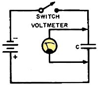
Fig. 2 - Theoretical circuit for measuring voltage drop across a capacitor.
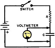
Fig. 3 - Circuit of Fig. 2 with "hidden" resistances of circuit shown as R.
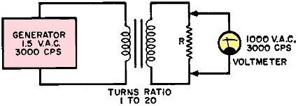
Fig. 4 - This circuit appears to defy the turns-ratio rule of transformer voltage output. See text.
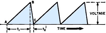
Fig. 5 - Sawtooth waveform output of the generator which utilizes self-induction for voltage boost. When an electrical engineering textbook speaks of an electric current as movement from plus to minus, the author is referring to the original convention (attributed to Benjamin Franklin) that was adopted before the discovery of the electron. Hence, he is defining an electric current not as a flow of electrons but as a motion of electrical energy in a direction opposite from that of electron drift. The surprising part of this dilemma is that either approach may be used with perfect safety as long as you are consistent. There is nothing wrong with defining the direction of an electric current as opposite from that of electron flow. If one wishes to stretch the imagination a bit, it can be shown that something does seem to travel backward as electrons travel forward (Fig. 1). Suppose that a row of pennies - simulating electrons - are laid end to end in a straight line. The penny at the right is moved further to the right over a distance equal to its own diameter, leaving an equal-size gap behind it. The next penny is then moved to fill the gap, the third is displaced to fill the newly formed space, and so on. Obviously, as the pennies travel in one direction, the gap proceeds just as rapidly in the other! (This may seem to suggest an explanation of the motion of "holes" in transistors to some of you; actually, transistor action is considerably more complicated.) Thus, the "plus-and-minus dilemma" resolves itself into a question of words. Most people in electronics prefer to deal . with electron flow, particularly when working with vacuum tubes where the space current consists only of electrons. But the principal thing to remember is that either way of looking at it will work out in careful hands. Capacitor-Charging Paradox. When a capacitor is set up in a circuit like that of Fig. 2, it is readily evident that the voltage - as read by the voltmeter connected across its terminals - builds up slowly. If the capacitor is on the older of several thousand microfarads, it may require two or three seconds to acquire a full charge equal to that of the battery potential. This time lag, however, appears to contradict the fact that electrical energy is transmitted through wires at close to the speed of light! With this velocity involved, the battery voltage should appear across the capacitor instantaneously with the closing of the switch. Here, as we see, fact appeals to contradict observation. The solution to this riddle, as with so many others, lies in the omission of a not - too -evident fact: no electrical circuit can ever be entirely free of ohmic resistance. The internal resistance of the battery, the resistance at the connections and in the wires must be added to the total picture. Symbolizing these "hidden" resistances, as shown in Fig. 3, we can now explain the apparent paradox without difficulty. Resistance R represents the internal battery opposition, that of the switch contacts and other circuit connections, plus the resistance of the connecting wires. The voltmeter is clearly measuring the potential drop across one portion of the voltage divider comprising R and C. When the switch is first closed, the capacitor offers no opposition to the charging current because it has not yet taken on a charge that could buck the applied e.m.f.; also, the small magnitude of R permits a large initial charging current to flow. A large voltage drop therefore develops across R, leaving almost nothing for the capacitor. This explains why the voltmeter reads negligible voltage at the beginning of the process. As the current flows into C, however, the latter begins to build up a charge and, consequently, starts to develop a back-e.m.f. that opposes the charging current. Hence, the current diminishes slightly, the voltage drop across R likewise decreases, and the voltmeter now reads a higher potential across the capacitor. This process continues until the counter e.m.f. in the capacitor becomes equal to the battery voltage. At this point, the charging current ceases, the voltage drop across R becomes zero, and the capacitor shows the same potential as the battery. Thus, although the transfer of electrical energy from the battery may take place at high velocity, the charging of a capacitor is a matter of quantity of charge rather than speed of particle motion. Sky-Rocketing Voltage To the novitiate in electricity, an ordinary power transformer at first appears to violate the fundamental law of energy conservation because it can "step up" voltage and thereby seems to give "something for nothing." Later, when he finds that the current output of a transformer diminishes in the same proportion as the voltage is stepped-up, the beginner is ready to accept the turns-ratio-voltage-increase relationship: secondary voltage = primary voltage x number of secondary turns / number of primary turns. Now our beginner is satisfied that a transformer can step up 100 volts to 500 volts if the secondary has five times as many turns as the primary. The current in the primary will be greater than five times the secondary current, and thereby makes up for the voltage gain. But once having understood all of the above, imagine his discomfiture when he reads about a circuit (Fig. 4) that will produce more titan 1000 volts across the secondary with only 1-1/2 volts applied across the primary winding, the transformer having a turns ratio of only 1 to 20! According to his figures, the output voltage ought to be about 30 volts, not 1000 or more. That is: secondary voltage = 1.5 x 20/1 = 30 volts. "No!" he says, "This can't be! But wait a minute ..." he adds as a thought strikes him, "the frequency of the a.c. in this circuit is 3000 cycles per second. Can that be the answer?" Looking back at the turn-voltage equation, it is evident that frequency has nothing to do with the question since it does not even appear in the relationship. This leaves him in a real quandary. Is the equation wrong or is the author of the circuit trying to pull someone's leg? The answer lies in neither of these possibilities. The author committed the unforgivable blunder of omitting to mention that the waveform of the input voltage was a sawtooth rather than a sine wave. In the circuit upon which this discussion is based, a transistor blocking oscillator was employed as the source of primary e.m.f. The d.c. source was a 1.5-volt dry cell. The setup ratio is actually 20 to 1, and the transformer-induced secondary voltage is only 30 volts as predicted by the transformer equation. But the sawtooth waveform is the secret of the sky -rocketing output voltage that appears across the load resistor R. It works this way: Line AB in Fig. 5 shows how the voltage across the primary slowly climbs from zero to its peak value during time t1. The same waveform appears in the secondary winding, only it is amplified 20 times by the step-up turns ratio. When the applied potential reaches its peak at B, it drops sharply down to zero once again, this time in a very short interval (t2). The magnetic field built up in the transformer during t1, therefore cuts swiftly back through the turns of the windings and induces a new voltage of much greater magnitude than existed there before. This voltage of self-induction has nothing to do with the turns-ratio of the transformer. Its size is dependent only upon the sharpness of magnetic field cutoff; the smaller the interval t2 is, the greater will be the self-induced voltage in any given transformer. Thus, it is perfectly practical to obtain a voltage gain which far exceeds that predicted by the transformer equation when the primary a.c. has sawtooth or rectangular waveform. Perhaps you, as a reader, have never been bothered ' by the dilemmas and paradoxes we have just described. It is more than likely, however, that you have been bewildered by others (and maybe still are). If they apply to electricity or electronics, write and tell us about them. "After Class" Topics
|
|||||||||||||
 |
|||||||||||||
|
|||||||||||||
 The disturbing thing about logical quandaries
is that they often form an insecure foundation for knowledge that is later to come.
Start with one wrong concept and you are likely to find that your entire superstructure
is unsound. The way to avoid a tragedy like this is to think your way through conceptual
problem situations at the very beginning.
The disturbing thing about logical quandaries
is that they often form an insecure foundation for knowledge that is later to come.
Start with one wrong concept and you are likely to find that your entire superstructure
is unsound. The way to avoid a tragedy like this is to think your way through conceptual
problem situations at the very beginning. 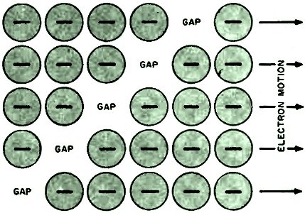

|
||||||||||||||||||||||||||||||||||||


