|
May 1955 Popular Electronics
 Table of Contents Table of Contents
Wax nostalgic about and learn from the history of early electronics. See articles
from
Popular Electronics,
published October 1954 - April 1985. All copyrights are hereby acknowledged.
|
By the time most of us who
even remember cathode ray tubes (CRTs) were first introduced to them, the technology
and manufacturing processes had been pretty much perfected - especially for the
standard 525-line (or 625-line outside the U.S.) resolution type. The National Television
System Committee (NTSC)
published a standard for black and white (B&W) television in 1941 and then for
color in 1953. This "Picture Tubes" article in a 1955 issue of Popular Electronics
provides a look inside a CRT manufacturing plant at General Electric. For some
reason the photos in the magazine were very poor quality (maybe for secrecy).
If you want one of the best explanations I have ever seen on how a TV picture
scan is implemented, check out this video entitled
What is
525-Line Analog Video?
If you don't understand raster scanning after watching it, you never will. You might
be surprised to learn that there were not actually 525 lines of picture information,
but that only about 480 to 487 lines of picture were included - the rest were for
scan synchronization, retrace and blanking, and special signal information. In fact,
the modern 480i digital standard evolved from that 480 lines of picture info. You'll
also learn a little about how video game consoles repurposed the NTSC scan format
to facilitate faster video updates.
See also How the Cathode-Ray Tube Works,
Picture Tubes,
TV X-Rays,
TV X-Rays Are Back.
Picture Tubes

The first step in actual processing of a picture tube is screening,
in which the phosphor picture screen is applied to the inside of the bulb's face.
Note screens inside tubes at left. Hoses pour one mixture into bulb, other comes
later.

On the screening conveyor, picture tubes move slowly along as
the phosphor-silicate mixture settles inside of their face areas. At far end of
belt, tubes will be tipped, and water will be run off.

Careful inspections follow the picture takes all the way during
processing. Here as operator inspects phosphor screens on tubes after they have
been removed from the screening conveyor belt.

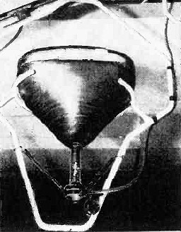
Electron gun, which later will be sealed into neck of a picture
tube, receives final inspection after assembly. At bottom are leads and glass tubulation
of stem assembly. Above, in order, are grid No. 1, grid No. 2, and metal sections
of anode structure. At top is focus electrode, the "getter," etc.

Processing "en route" takes place as completed tube is "aged"
on a conveyor taking it to final test section. "Aging" is process whereby electrical
characteristics are stabilized in tube.

"Merry-go-round" rotary aluminizer automatically coats interior
of tube bulbs with film of aluminum four one-millionths of inch thick. In finished
tube, this metallic layer on the back of the phosphor screen will reflect increased
illumination for brighter pictures and better contrast. Machine handles 24 tubes.

After all of its processing, the picture tube bulb is now ready
for installation of its electron gun. Step is performed on this rotary gun-sealing
machine by welding process.

Almost completed, the picture tube is swung from automatic "tip
off" machine after being pumped out to a vacuum and sealed at end of its neck. Later
the base is added and the tube completed.

Final inspection of the picture tube consists of checking it
for electrical stability, short circuits, brightness, and gas. Operator adjusts
standard test pattern on a 21-inch picture tube.

In place in a home receiver chassis, the picture tube is checked
before the completed unit is installed in a cabinet. Unit around neck of tube deflects
electron beam to sweep the screen.

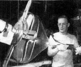
A "double-jointed" paintbrush, which bends after insertion through
the bulb's slender neck, coats entire cone of nonaluminized bulb with an electrically-conductive
paint as the bulb is rotated.

Into the bakeout oven's 350 degree C heat go the picture tube
bulbs after screening and aluminizing or inside painting. Here heat removes the
moisture and gas from these prepared tube bulbs.
The "heart" of your television set is the incredibly complex C-R tube. Here is
how it is made.
Do you take your television receiver so much for granted that you never wonder
about the complex circuitry and the vast amount of engineering "know-how" that is
represented in your living room?
One of the most fascinating components in your television receiver is the picture
tube itself. While this is almost the only "internal" component that everyone gets
to see, very few televiewers know how it is constructed or what is involved in the
manufacture of such a tube.
The photographs on this and the two succeeding pages show how such tubes are
"built" at the General Electric Company plant in Buffalo. This factory now turns
out thousands of picture tubes each day - including the 21-inch size.
The mass production of picture tubes is no simple proposition, but the operation
isn't as much a difficult effort as it is a delicate one. Every step of the operation
must be carefully controlled.
Every part that goes into a tube must be checked and inspected all the way through
production. The finished tube must meet exacting standards before it is shipped
to a set manufacturer or released for replacement applications.
Basically, a picture tube is a conical glass bulb with a phosphor screen on the
inside of the bulb face. Mounted in the neck of the bulb is an electron "gun" whose
electron beam is directed at the screen to activate it and reproduce the transmitted
image.
The metal electron gun parts, including units about the size of a thimble, magnets
not much larger than a pencil eraser, and tungsten wire finer than a human hair,
are weighed, measured with fine-precision gauges, or inspected on a shadowgraph
which projects their silhouettes, magnified 20 times, on a translucent screen.
These various components eventually emerge as a television picture tube after
going through the processes which are pictured in the photographs accompanying this
article.
During 1955, General Electric statisticians estimate that over 11,750,000 picture
tubes will be manufactured, 5,600,000 of which will be earmarked for replacements
in existing television receivers. The percentage of color TV picture tubes will
still be relatively small, with the prediction, as of now, at about a quarter of
a million tubes for the multi-hued television sets.
The next time you step up to your TV set to turn on your favorite program, take
a long, hard look at the "Cyclops" staring out at you. It is an eye-opener if you
will only take the time to examine this electronic eye to your world of entertainment,
education, and sheer fun. It can truly be classed as an "electronic miracle" of
the first order.
|


