  Amplitude modulation uses the instantaneous amplitude
of a modulating signal (voice, music, data, etc.) to directly vary the amplitude of a carrier
signal. Modulation index, m, is used to describe the ratio of maximum voltage to
minimum voltage in the modulated signal. If the modulating signal is equal in magnitude to
the carrier, then m = 1 and the modulated signal varies from a scaled maximum of
unity down to zero (see figure below). When m = 0, no modulation of the carrier is performed.
If m is greater than 1, the carrier is actually cut off for some period of time,
and unwanted harmonics are created at the transmitter output. Amplitude modulation uses the instantaneous amplitude
of a modulating signal (voice, music, data, etc.) to directly vary the amplitude of a carrier
signal. Modulation index, m, is used to describe the ratio of maximum voltage to
minimum voltage in the modulated signal. If the modulating signal is equal in magnitude to
the carrier, then m = 1 and the modulated signal varies from a scaled maximum of
unity down to zero (see figure below). When m = 0, no modulation of the carrier is performed.
If m is greater than 1, the carrier is actually cut off for some period of time,
and unwanted harmonics are created at the transmitter output.
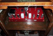
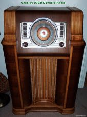
The pictures here are of my restored
Crosley 03CB radio,
which was manufactured in 1941, before commercial FM broadcast radio was still in the experimental
phase of development. This radio tuned the 540 to 1700 kHz AM band and the 16 to 49 meter
shortwave band.
| A |
360º |
25% |
Device is biased in to conduct in the linear region all the time. |
| AB |
> 180º, << 360º |
--- |
Two devices connected like a Class B, but biased to conduct somewhere between Class A
and Class B. |
| B |
180º |
78.5% |
Two devices in series with the output taken at the common junction. Both devices biased
to conduct in the linear region for opposite half a cycle, i.e., they are never on at the
same time. |
| C |
> 0º, < 180º |
--- |
Device is biased to turn on after a certain input threshold voltage is exceeded. Very
efficient, but creates distortion. |
| D |
|
100% |
Used to switch completely on or completely off. |
| E |
|
|
Used for rectangular input signals. |
In the frequency domain, the carrier frequency is flanked on both sides by mirror image
copies of the modulating signal.
ΩM1 = Ωc ± ωm1,
ΩM2 = Ωc ± Ωm2

Let the carrier be xc(t) = Xc·sin (Ωct), and the modulating
signal be xm(t) = Xm·sin (ωmt)
Then x(t) = Xc·[1+m·sin
(Ωmt)]·sin (Ωct)
In the following examples, the carrier frequency is nine times the modulation frequency.
Red (dashed) lines represent the modulation envelope. Blue (solid) lines represent the modulated
carrier.
|
 Here, the maximum
voltage (Vmax) is 2 V and the minimum (Vmin) is 0 V. From the modulation index formula: Here, the maximum
voltage (Vmax) is 2 V and the minimum (Vmin) is 0 V. From the modulation index formula:

|
|
 Here, the maximum
voltage (Vmax) is 3 V and the minimum (Vmin) is 1 V. From the modulation index formula: Here, the maximum
voltage (Vmax) is 3 V and the minimum (Vmin) is 1 V. From the modulation index formula:
|
|
 Here, the maximum
voltage (Vmax) is 1.25 V and the minimum (Vmin) is 0.75 V. From the modulation index formula: Here, the maximum
voltage (Vmax) is 1.25 V and the minimum (Vmin) is 0.75 V. From the modulation index formula:
|
|
 Here, the maximum
voltage (Vmax) is 2.5 V and the minimum (Vmin) is -0.5 V. From the modulation index formula: Here, the maximum
voltage (Vmax) is 2.5 V and the minimum (Vmin) is -0.5 V. From the modulation index formula:
|
Note: AM waveforms created with MathCAD 4.0 software.
Related Pages on RF Cafe - Amplitude
Modulation - Frequency Modulation -
Quadrature (I/Q) Modulator Sideband Suppression -
Bessel Functions & Graphs -
Modulation Principles, AM Modulation,
NEETS - Modulation Principles,
FM Modulation, NEETS - Modulation
Principles, Demodulation, NEETS - Frequency Mixer, Converter, Multiplier,
Modulator Vendors
|