|
|||||||||||||
 |
|||||||||||||
Reed Relays
|
|||||||||||||
This April 1967 edition of Electronics World featured a handful of articles covering different types of relays and circuits for controlling them: reed relays, time-delay relays, stepping relays, mercury-wetted relays, resonant reed relays, operate and release times, relay coil considerations, and more. Even with the advent of transistor switching, there are still many uses in modern circuits for electromechanical relays, so this material should prove useful. Here are links to the other relay articles: Operate and Release Times of Relays, Reed Relays, Time-Delay Relays, Finding Relay Operate and Release Times, Arc, Surge, and Noise Suppression Reed Relays
The author graduated from Drake University in 1961. He joined C.P. Clare & Co. as an applications engineer in September of 1963. By Roger L. Rosenberg/Systems Project Engineer, C.P. Clare & Co. Long electrical life resulting from precious-metal contacts sealed in inert atmosphere and absence of wearing mechanical parts are the most important advantages of this increasingly popular relay type. Within the last ten years the reed relay has become recognized as a reliable, low-cost switching device. The apparent simplicity of the reed relay probably influenced some designers to use it, but its more subtle features have increased its popularity. Long electrical life resulting from precious metal contacts sealed in an inert atmosphere and absence of wearing mechanical parts head the list. The relatively high speed and varied package configurations give it advantages over conventional relays. The price of a reed relay begins in the $2 to $7 bracket, varying with the quantity, the number of contacts, the coil size, and the manner of packaging. Its low cost, high circuit isolation, and insensitivity to noise make it an ideal replacement for electronic switches in many applications. The heart of the reed relay is the reed switch. Discussion of reed relays must begin with the switch since the former can be no better than the switch it contains. To meet the demand, reed-relay manufacturers have had to automate their production. Automation of reed-switch manufacturing has required much tighter control of all components and a better understanding of what is required to make consistently good switches. As designers found new applications, manufacturers had to develop both new design and new processes. The pressurized reed switch and mercury-wetted reed switch, along with varied contact material, have resulted. The simplicity of the switch belies the sophisticated technology required to manufacture switches with consistent electrical and mechanical properties. A description of the reed switch and its operating parameters will help illustrate the need for this control and technology. The Reed Switch The basic reed switch is a normally open contact. It consists of two ferromagnetic reeds, each of which is sealed in an end of a glass tube. The reeds are positioned so that heir free ends are overlapping (typically 1/16 in) and are separated by a gap (between 0.005 and 0.012 in). These reeds constitute the magnetic circuit of the switch. When a magnetic field is introduced to the switch, the reeds become flux carriers. The overlapping ends assume opposite polarities and attract each other. If the attraction is strong enough to overcome the deflection characteristics of the reeds, they will move together and touch, making electrical contact. For consistent contact resistance the overlapping ends reeds are precious-metal plated. The contact plating must be thin and uniform so that the magnetic properties of the switch are not adversely affected. If the plating is too thick, the magnetic gap will be too great to insure sufficient contact pressure and will result in a high release characteristic. The field strength required to close the switch depends on the size of the reeds, the effective gap (atmosphere and plating) between them, and the amount of overlap. Small changes in any of these parameters can significantly alter the operating characteristics of the switch. These factors must all be controlled to insure the consistent characteristics necessary for designing the switches into relays. Other factors which must be controlled to obtain consistent and reliable operations are blade alignment, contaminants in the gas, and seal integrity. The amount of power required to operate a reed switch is typically 125 mW. The more power applied, the faster the reeds will close, until the saturation point of the reeds is reached. The maximum speed is typically 0.8 ms, but this is usually impractical in most circuit applications because of the power requirements. Contact bounce is also increased when the switch is driven hard, so speed should never be considered alone. Contact life is affected by contact bounce, the load switched, and the repetition rate. End of contact life, however, can only be determined by the circuit requirements. The load which can be handled by the reed switch depends on the contact material, the number of operations expected, and the failure criteria. The most common contact material is plated and sintered gold. This contact has a relatively high rating of 15 VA and a life in excess of 20 million operations. Plated bright gold contacts can perform well with low-level loads because of their low and constant contact resistance. Bright gold presents a hazard, however, in that the closed contacts may fail to release because of a phenomenon spoken of as "particle migration" or "cold welding". Rhodium contacts appear good on both high- and low-level loads. Difficulties in controlling the plating can result in inconsistent switches. Tungsten contacts are good performers in switching high loads such as lamps and solenoids. "Mercury can be used to coat one of the reeds so that it becomes a fluid contact. It eliminates operate bounce and maintains a constant, low contact resistance. The switch becomes position-sensitive since the mercury is fed up the lower reed by capillary action from a mercury pool at the bottom of the switch. (Note that one of the reeds is dry as contrasted to the mercury-wetted contact relay, discussed elsewhere, in which all contacts are wetted by mercury.-Editor) While the basic switch is a normally open contact, other forms are available. The normally closed contact is made by affixing a permanent magnet of sufficient strength to close the switch. The operating flux must oppose the magnet sufficiently so that switch will open and remain open as long as the operating flux is present. "Break" and "make" can be accomplished by combining a normally open and a normally closed switch in the operating coil. The normally closed contact can be adjusted by magnet biasing so that break-before-make operation can be achieved. Break-before-make is also available in a single capsule. The break contact is accomplished by magnet or spring biasing the armature or swing contact to one of the stationary contacts. The most commonly used reed switches are: Standard Dry Reed Switches
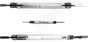
Fig. 1 - (Top) A standard dry reed switch. (Center) Miniature or micro dry reed switch. (Bottom) Mercury-wetted reed switch. These mercury-wetted types of switches, because of a pool of mercury at one end, must always be used in vertical position. The standard reed switch, Fig. 1 (top), is approximately 3 1/4 in long by 7/32 in in diameter. It has plated and sintered gold contacts and is rated at 15 VA resistive (250 V maximum, 1 A maximum. Contact resistance initially is less than 50 milliohms. The standard switch will withstand shocks of 11 milliseconds' duration to 40 G peak without false operation. Micro Dry Reed Switch. The micro, or miniature. reed switch, Fig. 1 (center), is approximately 15/8 in long and 0.10 in in diameter. It is rated at 10 VA resistive (200 V d.c. maximum, 750 mA maximum). Initial contact resistance is typically 100 milliohms. The micro reed can withstand shocks of 11 ms duration to 50 G peak without false operation. Mercury-Wetted Reed Switch The mercury-wetted reed switch, Fig. 1 (bottom), is approximately the same size as the standard reed switch. It is rated at 50 VA resistive (200 V maximum, 2 A maximum). It is position-sensitive and must be mounted within 30° of vertical. High-Voltage Reed Switch. The high-voltage reed switch has the same dimensions and contact rating as the standard reed switch. It is pressurized to achieve the high stand-off rating of 1500 V r.m.s. Special reed switches with standoff voltages to 5000 V peak are available. Reed Relay The reed relay is made by enclosing one or more reed switches in an operating coil. The coil is usually wound on a bobbin made of nylon or other similar material. The bobbin may also have anchors or pins for attaching the coil leads and reed switches. The number of capsules to be placed within the coil determines the bobbin size. Most manufacturers limit the coil to handle 12 of the standard reed switches. Above this size proper operation of all switches is limited by the efficiency of the coil. Different contact forms can be combined in the same operating coil so that contact configurations such as 12A, 8B, or 4C or combinations of these are possible in a 12-switch coil. Because the coils are wound on bobbins of a certain size, the resistance and turns of coils offered are determined by wire sizes. For a given bobbin, the turns and resistance will vary with each wire size and thus the operating voltage of the relay will change with each wire size for switches with the same operate characteristics. For example, a one-switch bobbin wound with #29 wire has 1200 turns and a resistance of 10 ohms while the same bobbin wound with # 42 wire has 22,200 turns and a resistance of 3750 ohms. The coil power required to operate the relay is determined by the number and configurations of contacts and by the operating speed required. A typical single form A relay will require approximated 125 mW, a 5 form A relay, approximately 450 mW. Most open-type relays will dissipate 4 watts in 25° C ambient. The maximum dissipation of the relay will depend on the coil wire insulation and construction materials. No matter what package configurations the coil and reed switches acquire, there should be no stresses on the reed blades. Stresses can fracture the glass-to-metal seal on the switch and result in an early failure. Another factor which should be considered in the final package is shielding. Shielding of the relay can improve its characteristics and eliminate its influence on other relays or avoid its being influenced by them. Magnetic flux of one relay might actuate an adjoining relay. This can be significant when sensitive relays are packed closely together. Relay-Application Considerations The load to be switched must be evaluated so that the proper reed switch can be chosen. Loads such as lamps which have a high in-rush current can reduce life. Such schemes as having a resistance in the lamp circuit to keep it hot but dim can add millions of operations to the reed switch. Suppressing an inductive load also extends contact life. Contact protection such as an RC network can be applied, but is required only when the load exceeds the published ratings or when life expectancy must be extended. After the proper switch has been chosen, the next consideration is to select the best package for application. The reed relay may be potted in a can and fitted with an octal-type base for chassis mounting. Other special packages are made.
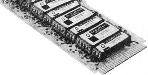
Fig. 2. An assembly of reed relays on a printed-circuit board. The most popular means of mounting the reed relay is on printed-circuit boards. Its low profile and contact termination adapt it very well to such mounting. The coil bobbin is usually fitted with terminals which make the relay easy to install and give protection to the reed switches. A typical example of a reed relay printed-circuit board assembly is shown in Fig. 2. This 4 1/4" x 10 7/8" board, having five counting stages, can be mounted on 25/32" centers. The reed switches are replaceable in this type of assembly if a change is required. For severe environments the relay may be potted or molded into special configurations. An epoxy-molded assembly is available for printed-circuit board mounting. The open-construction relay is quite adequate for most industrial applications. These relays will operate over a temperature range from -65° C to 85° C. Special assemblies are made to operate to 125° C. The minimum breakdown voltage is typically 500 V r.m.s. 60 Hz, and the insulation resistance is greater than 100,000 megohms. Magnetic shields are supplied on the relays in most cases. Even with shields, the relays should not be located close to any device which can generate a strong magnetic field. The reed relay, if properly chosen. does not require a close-tolerance power source. One with a tolerance of ±10% is adequate for most applications. When choosing a relay for an application, the worst-case power and temperature conditions must be considered together with the most unfavorable coil-manufacturing tolerance. If under worst-case conditions the available power diminishes to approach the just-operate value of the switches, the operate time will increase. Reed switches release in less than a millisecond in most relay assemblies. If the coil is shunted by a diode or by an RC network, however, the release time may reach several milliseconds. High insulation resistance requires special materials and handling during the manufacture of the relay. Relays with insulation resistance greater than 500,000 megohms have been made in different configurations. Higher break-down voltage requires special assemblies. Circuit Considerations After the relay has been chosen it must function in the circuit. The fast operate-time of reed switches can become a problem unless care is taken to insure that the drive pulse is free from "grass" or discontinuities. If the discontinuities are long enough to allow the reed switch to release, random faults can occur. It is recommended that reed-switch counters, shift registers, etc., be driven by a mercury-wetted contact relay which has been buffered against possible discontinuities. When the coil is de-energized and the reeds move apart, they swing through their neutral position and oscillate at their resonant frequency until all their energy is dissipated. Unless the switches are damped, the application of a holding voltage during this oscillating period can cause the reeds to reclose. An "off" time sufficient to insure the settling of the reeds is required to provide proper operation and repeatable timing. To get the maximum number of operations from the reed switch every opportunity to first establish the path and then switch the load with a single heavy-duty contact should be explored. The most reliable circuits are those which use a combination of coil and switch logic. An example of this is the binary-coded decimal counter in which none of the contacts switch a load; they only perform the steering function for the count pulse. The output contacts can also be connected so that they can be strobed by a single contact thus insuring the same long life for them. The addition of RC networks can make reed relays slow-release or slow-operate and slow-release. If the relay which is to be slowed has several switches, staggered operate and release can occur. The interposing of a single form A contact relay, having the proper delay network, to drive the multi-contact relay will solve the problem. Since the relay which now has the delay has a higher resistance, lower capacitance is needed. Special Relays Reed relays with multiple wound coils yield all of the basic logic functions and numerous special devices. Reed-relay two- and four-state flip-flops can perform all of the standard counting functions at speeds more than adequate for most industrial applications. One of the most popular special relays is the magnetically latching or hi-stable relay, the windings of which are connected to oppose each other. A magnet is adjusted to a level not sufficient to close the reed but strong enough to hold it closed. The winding which aids the magnet is the "set" winding. The one opposing is the "release" winding. Voltage applied to the "set" winding causes the reed to close. When the voltage is terminated, the magnet holds the reed closed. Voltage applied to the "reset" coil opposes the magnet flux causing the reed to open. Reed relays are used in a variety of industrial control devices, in telephone switching, materials handling, and in manufacturing automation. They provide the true isolation between input and output of a contact device, yet perform faster than conventional electro-mechanical relays. They permit multiple inputs, thus enabling logic to be performed by both the coils and contacts. Mercury-Wetted Relay Contact Protection
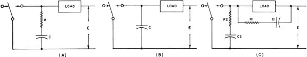
In the following discussion, the value of the capacitor (in microfarads) can be found from C = I2/10, where I is the current in amperes immediately prior to contact opening. The value, in ohms, of the associated resistor can be found from R = E / (10I)α. where E is the source voltage just prior to contact closure and α = 1 + (50/E). Where E is less than 70 volts, R may be three times the calculated value; where E is greater than 70 volts, but less than 100 volts, R may be ±50% of the calculated value; where E is greater than 100 volts but less than 150 volts, R may be ±10% of the calculated value; and where E is greater than 150 volts, R may be ±5% of the calculated value. In all cases, the minimum value of R is 0.5 ohm, and the minimum value of C is 0.001 µ.F. The arc suppressor shown in Fig. A is suitable for most load switching demanded of mercury-wetted contact relays. If desired, the value of the capacitor may be increased as much as 10 times to help reduce voltage transients of inductive loads. When contact load current is 0.5 A or less, and the source voltage is 50 volts or less (peak values for a.c. circuits), the resistor may be eliminated as shown in Fig. B. The capacitor value must not exceed the calculated value. For certain extreme loads, such as highly inductive a.c. loads at voltages above 100 V a.c., it may be desirable to place the main RC arc suppressor (R1-C1) across the load as shown in Fig. C. This alleviates the problem of a.c. leakage current through an RC arc suppressor in parallel with the contacts, but may result in a condition which exposes the contacts to voltage transients having a rate of rise in excess of 5 V/μs maximum, due to the inductance of the lead wires. A secondary arc suppressor (R2-C2) must then be included across the contacts. However, a.c. leakage across the contacts is markedly reduced since C2 need only be one-hundredth of the calculated value. Both resistors should be the calculated value although the value of C1 may be increased up to 10 times the calculated value to further reduce transients. |
|||||||||||||
 |
|||||||||||||
|
|||||||||||||


|
||||||||||||||||||||||||||||||||||||


