|
June 1931 Radio-Craft
 [Table
of Contents] [Table
of Contents]
Wax nostalgic about and learn from the history of early electronics.
See articles from Radio-Craft,
published 1929 - 1953. All copyrights are hereby acknowledged.
|
This reactance measuring bridge
circuit which appeared in a 1931 issue of Radio-Craft magazine employs
a very unique element for generating an alternating current: an electromechanical
buzzer which doubles as an audio source. Sure, it doesn't produce a pure sinewave,
but for the method used here to determine inductance and capacitance it does not
matter. Rather than attempting to measure an absolute value of inductance or capacitance,
a known reactance is used as part of a balanced bridge. This is by no means a precision
instrument since accuracy depends on the user's interpretation of the presence or
absence of an audible "buzz" in a pair of headphones, but in an era when "real"
test equipment was beyond the budgets of many (maybe most) hobbyists, the scheme
was better than nothing at all. This reminds me a bit of the "Bumble Buzzer" continuity
checker we used at the Westinghouse Oceanic Division in the 1980s for "buzzing out"
multiconductor cables; it was in a black and yellow plastic project enclosure and
emitted an audible buzz when the measured resistance was below a certain value. See also
National Radio
Institute advertisement, December 1954 Radio News;
Mathematics in Radio in July 1932 Radio News;
Measuring Inductance and Capacity, June 1931 Radio-Craft;
Mathematics in Radio,
March 1933 Radio News;
Radio Frequencies and Their Allocation, June | July 1940 National Radio News;
Your Radio Training and the Defense Program, December 1940 | January 1941
National Radio News.
Measuring Inductance and Capacity
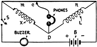
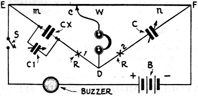
Fig. 1 - The simple bridge, with buzzer and phones, for
measurement of inductance.
How the Experimenter May Utilize a Reactance Bridge
By James A. Dowie*
In the February issue of Radio-Craft appeared a description of the construction
of a Wheatstone bridge which could be used to measure unknown resistances, such
as are used in radio work. ("A Home-Made Slide-Wire Bridge,"
by A. W, Bonser, page 482). The object of this article is to show how the
Wheatstone bridge may be used also to good advantage by radio-tricians and Service
Men for making various measurements of inductance and capacity - two important factors
necessary for satisfactory reception of radio signals. Inductances, as used in radio
work, function under alternating current; therefore, measurements should be carried
out with alternating current.
Fig. 1 shows the circuit arrangement used in this bridge. In series with
the battery "B," a buzzer is placed; and the combination is utilized to give an
alternating current through the various arms of the bridge. (A high-frequency buzzer
or a vacuum-tube A.F. oscillator, such as have been described in Radio-Craft, may
also be used for this purpose.) With this arrangement a pair of phones serves as
the indicating device; they are connected as shown in the diagram. If audio-frequency
current flows through the phones, a sound will be heard; while, if no alternating
current flows, no sound is heard. The Wheatstone bridge is then balanced by sliding
the contact c over the arms m, n of the bridge until a minimum of sound is heard;
this is the condition of balance.
(Note: "Minimum" sound is specified; because it may be impossible to obtain a
zero sound-balance with this apparatus, on account of induction and stray capacity
effects. Knowing this, we will now consider the case of measuring the inductance
of a coil by means of such an arrangement.).
Measurement of Inductance
In the circuit arrangement of this bridge used for inductance measurements, m
and n are the slide-arms of the bridge; c is the sliding contact; L the known inductance,
and X is an unknown coil whose inductance is to be measured.
This circuit is in theory the same as that used in the resistance measurement,
described in the preceding article; when the slider c is moved along m and n until
a balance is obtained, a minimum sound will he heard in the telephones. Then the
following relation is true:
Thus, if a single standard inductance L and a slide-wire bridge with phones,
battery and buzzer are available, the values of unknown inductances may be easily
measured.
This relationship is only true in practice when the unknown inductance X is of
the same order of magnitude as the standard inductance L. By this it is meant that
inaccuracies will arise in these measurements if the standard inductance is about
0.1 millihenry, for instance, while the unknown inductance is 10 millihenries; because
the ratio of m to n would then be too great to obtain an accurate balance. If the
ratio of m and n is about 1 or 2, then a sharp balance will be had.
The following notes should be of interest to radio-tricians interested in accurate
measurements with a bridge:
The formula given above for inductance is sufficiently accurate for all practical
purposes; however, it does not take into consideration the resistance of the inductance
coils. If there is a great discrepancy between the resistances of the two coils
L and X, it is quite possible that a sharp balance will not he obtained. Balancing
a Wheatstone bridge circuit is something like tuning a radio receiving circuit;
since resistance in a resonant radio circuit makes for extremely broad tuning.
Balancing a Wheatstone bridge is equivalent to reducing the resistance, and thus
enables sharp balance or tuning. If the resistances of the coils are not balanced,
a sharp balance will not be secured and, therefore, the accuracy of the measurement
will be destroyed; since the accuracy of the measurement in a Wheatstone bridge
depends upon the sharpness of the balance.
Correction for Resistance
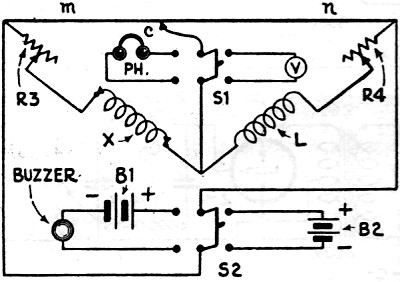
Since all inductance coils have some resistance, a better arrangement of the
bridge is shown in Fig. 2, where each coil has its compensating resistance
(R3, R4) in series.
For precision measurements, it is necessary to strike a balance for both the
inductances and the resistances of the coils. The inductance balance is secured
by means of the buzzer and headphones; while the resistance balance is secured by
a voltmeter and the battery B2 for the source of supply. In this bridge, Fig. 2,
we use two double-pole double-throw switches (S1 and S2); one is used for switching
on either the voltmeter V or the phones PH for the balance indicator. (The potentials
of B1 and B2 must be found by experiment).
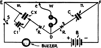
Fig. 2 - The bridge arrangement for balancing inductance
and resistance to obtain a true reading of the former.
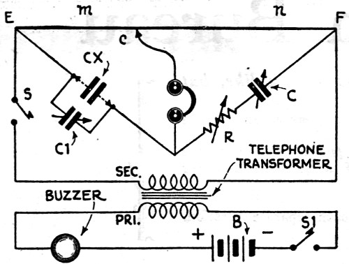
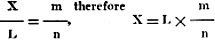
Fig. 3 - Use of the bridge for capacity measurements, with
the necessary compensation for zero setting.

Fig. 4 - The circuit connections of a Wheatstone bridge
using a high-frequency buzzer, for accurate measurements of capacity.
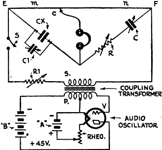
Fig. 5 - The most satisfactory operation of the bridge is
obtained with an A.C. oscillator giving a good note.

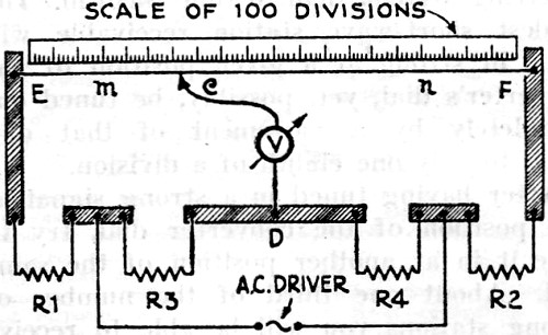
Fig. 6 - A wooden base, 8 x 45 inches, will mount a one-meter
rule as shown; or the "reciprocal" scale of the February article may be used.
The buzzer and phones are used for the A.C. inductance balance, with switches
S1, S2 thrown left; the battery and voltmeter, for securing a D.C. resistance balance,
the switches thrown right. The variable resistors, R3, R4, placed in series with
each of the inductances enable us to balance the inductance arms for resistance.
The following gives the method used for operating this type of bridge circuit.
First, a balance is obtained for the A.C. signal; the double-pole, double-throw
switches are both thrown to the left, to use the buzzer and phones. The sliding
contact c on the wire m-n is varied until a balance is obtained. The switches are
then thrown to the right to place the battery and voltmeter in the circuit. With
the sliding contact c fixed at the position previously obtained, vary the resistance
of R3 and R4 until the voltmeter v indicates a balance, by zero deflection. Now
switch over again to the buzzer and phones, and vary the position of the sliding
contact until a balance is obtained, as indicated by a minimum sound in the phones.
Again switch back to battery and voltmeter, keeping the sliding contact c fixed
in the new position previously found; and very the resistors R3 and R4 until a balance
is obtained. Alternate this way until a very sharp balance is obtained on both D.C.
and A.C. - then note the values of m and n and apply the formula previously given.

It will be noted that the important adjustment of the sliding contact c was not
changed in balancing the resistances of R3 and R4; since the important adjustment
of the slider determines the inductance measurement. The above formula is absolutely
correct and is based upon both types of balance thus obtained.
Measurement of Capacity
The Wheatstone slide-wire bridge may be used also to measure unknown capacities,
there being required in this circuit but one known capacity. Fig. 3 illustrates
the connections for this bridge; in which C is the known capacity and CX the unknown
capacity, while m and n are the lengths of the two arms of the slide-wire, which
are adjusted for a balance by a minimum sound in the phones.
It is evident that, with this arrangement, the resistance in one arm of the bridge
is balanced against the impedance of the condenser in the adjacent arm. (The impedance
of a condenser is the resultant of resistance and reactance but, as the resistance
is so very low, compared to the reactance, it can be disregarded and the entire
impedance considered as reactance.)
The reactance of a condenser varies inversely as its capacity; while the reactance
of an inductance varies directly, and therefore the preceding formula must be rewritten
and used in the following form:
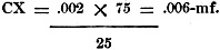
For example, the scale has 100 divisions and the sound is minimum in the phones
at a point on the wire 25 divisions from E (Fig. 6); leaving 75 divisions for
n, between F and c. Assuming that we use a standard capacity value of 0.002-mf.
for C, we may substitute these values, giving
In all these measurements using a buzzer to supply the alternating current to
the bridge, it is advisable to set the buzzer at some distance from the bridge,
or muffle it in some wav; for otherwise it will be difficult to determine whether
the sound is coming from the phones and due to the current passing through them,
or whether it is direct noise from the buzzer. (A "high-frequency" buzzer is more
quiet. See Fig. 4.)
An excellent source of A.C. voltage for measuring inductance and capacity is
a vacuum-tube audio-frequency oscillator which does not have the above-mentioned
fault of buzzers. The terminals of the oscillator are connected to the points E
arid F of the bridge. (See Fig. 5) Resistor R1 controls the amount of A.C.
fed to the bridge.
In these measurements, a calibrated variable (air dielectric) condenser may be
used as the standard C; with this, a very large range of unknown capacities may
be very simply measured.
First, the slider is set at the mid-point of the length of resistance wire, thus
making m equal to n. The variable condenser C is then adjusted until a balance is
obtained. Then, the dial reading of the standard condenser C will indicate the capacity
of the unknown condenser CX; since m and n are equal.
A midget condenser, C1, is necessary in this measurement so that a balance (at
the minimum capacity of C) may be had, and the zero reading of C taken without the
unknown condenser CX in the circuit. It is required also to bring the balance point
further up the scale on C when measuring small values of CX.
The effective resistance of the condensers enters into the measurement of capacities
exactly as in the measurement of inductances; but, in the case of condensers using
air as the dielectric, this is not very important because the resistance of such
condensers is almost zero. However, where condensers have different dielectrics,
(for instance, air, and "mud" compositions), there will be a considerable difference
in their resistances; which means that it will be impossible to get a silent point
in the telephones. However, a fair balance point can usually be secured.
Because of the insulating properties of condensers, the circuit will be open;
therefore, it is impossible to balance this bridge with direct current. However,
a good balance, with fair accuracy, is generally found when using the fundamental
circuit shown in Fig. 3.
In order ·to secure a more accurate balance with this bridge, it is necessary
to connect a variable resistor R in one or the other of the condenser arms, (X1
or X2, Fig. 3.); the proper place is found by trial. This will compensate for
any resistance effect introduced by the condenser in the other condenser arm. The
readings of this resistance, with and without the condenser CX, are indicative of
the losses in the condenser under test. This is a check-up of "leaky" condensers.
Construction of a Slide-Wire Bridge
The connections between the components of the bridge are made on the top of the
wooden base by means of brass straps 1 1/2 inches wide and 1/4-inch thick (Shown
in Fig. 6.). The holes for the terminals are tapped the correct size.
The wire used for m and n may be of any standard make of resistance wire (such
as nichrome, German silver, constantin, etc.) and its gauge from No. 24 to No. 28
B & S.; as these are the most convenient sizes with which to work. (Note: Be
careful to secure uniform wire, for the resistances of the two arms of the bridge
m and n are proportional to their lengths only if their cross sections are equal.)
The resistance wire is stretched taut almost flat on the board, and securely
fastened at E and F to the brass strap at each end of the bridge. The meter-scale
is mounted directly beneath the resistance wire, thus positioning the slide-wire
about 1/16-in. above the meter-scale. The contact slider c may be one of the sharp
edges of a 1/4-in. brass rod; the opposite edge being soldered to a length of rubber-covered
lamp cord. Compare Fig. 6 with Fig. 2.
* Chief Instructor, National Radio Institute
Posted June 28, 2022
(updated from original post on
8/25/2015)
|