|
August 1945 Radio-Craft
 [Table
of Contents] [Table
of Contents]
Wax nostalgic about and learn from the history of early electronics.
See articles from Radio-Craft,
published 1929 - 1953. All copyrights are hereby acknowledged.
|
The Barkhausen-Kurz (B-K) oscillator
is credited as being the first high power microwave generator that exploited the
electron transit time effect. It was developed in 1920 by German physicists
Heinrich
Georg Barkhausen and Karl Kurz. As this article's author points out, the vacuum
tube and supporting circuits were difficult to produce and were not very well understood
theoretically. Shortly thereafter, the magnetron and klystron tubes came along and
dominated the high power microwave generation realm. Included in Part II of
"Microwave - Generation of Microwaves" is a good, brief explanation of the
operation of both B-K and magnetron circuits.
Part I appeared
earlier in the July 1945 issue of Radio-Craft magazine.
See Microwaves Part I,
Part II,
Part III, and
Klystron: Tube of the Future.
Microwaves - Part II
Part II - Generation of Microwaves
By Captain Eugene Skinner*
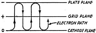
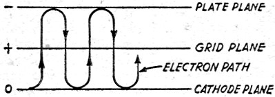
Fig. 1 - Electron paths in a B-K oscillator.
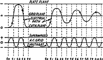
Fig. 2-a, left - Electron path, grid going positive. 2-b
- Same, grid going negative.
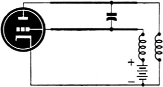
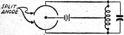
Fig. 3 - Complete Barkhausen-Kurz circuit.
Fundamentals governing the use of microwaves, and operation and applications
of the Klystron have been presented in previous articles. In addition to Klystron
tubes, there are other types of tubes and circuits which are used at microwave frequencies.
Two of the most important are the Barkhausen-Kurz circuits and the magnetron circuits.
While the Barkhausen-Kurz oscillator is largely an experimental one and is not
widely used in actual microwave applications, it is as basic a circuit for microwaves
as the Hartley oscillator is for ordinary frequencies, and an understanding of how
it works will give the amateur and the experimenter a better background for their
work.
Barkhausen and Kurz discovered a new type of oscillator in 1920. It is also known
as the B-K, retarding field, or positive-grid oscillator. This type of oscillator
has been used to generate ultra-high frequencies and microwaves up to a few centimeters
in length, and works on principles which are relatively simple when considered qualitatively.
Exact mathematical treatment is very difficult and does not lend itself to a better
understanding of the operation of the tube, so will not be touched on here.
Basically the tube itself consists of a single straight wire filament surrounded
by a cylindrical grill and plate. The grid may be of parallel wires, or it may be
of a number of wires twisted into a helical shape. The plate itself is merely a
cylindrical tube. This tube is a triode with the elements specially arranged.
For producing oscillations in this type of tube, the grid is positive instead
of negative. The plate, instead of being positive, is usually slightly more negative
than the filament, but may be at the same potential. Electrons from the filament
are accelerated toward the grid by its positive potential, most of them passing
through the meshes, and entering the field between the grid and the plate, where
they, being negative, are repelled by the negative or relatively negative plate.
They stop, reverse direction, and then accelerate back toward the positive grid,
which attracts them. Again, most of them pass through the grid, enter the field
between the filament and grid, where they are again repelled, this time by the filament
itself. They stop, and together with the new electrons which are leaving the filament
at that instant, start toward, then through the grid again. Each time that the electrons
pass through the grid, some of them are lost to it. Those which continue to oscillate
back and forth return to the grid each successive time with lower energy, and move
a shorter distance away from it. Eventually the electron strikes the grid and is
lost. This grid operates at a high temperature, and necessarily has to withstand
high power dissipation. Grid failure is the most common cause of failure of this
type of tube. The path of the average electron is shown in Fig. 1.
If an A.C. voltage that has a period approximately equal to the electron transit
time from the cathode to the plate is superimposed on the positive grid source,
it is possible to either extract energy from the D.C. source, or give energy to
it. Figs. 2-a and 2-b show typical paths of electrons for two conditions: Fig. 2-a
shows an average path when the electrons start from the filament at an instant that
the applied A.C. on the grid is going positive, therefore making the grid more positive
than it normally would be, and Fig. 2-b shows an average path when the electrons
start from the filament at which this applied voltage is going negative.
If the grid is more positive than normal, the electron is sped up. As the electron
approaches the plate, the A.C. voltage on the grid reverses, and the grid is less
negative, causing the electron to slow down less on its return trip. In a trip like
this, it is possible that the electron will strike the plate, but if it does not,
it returns to the grid or cathode. As the electron has been sped up during its entire
trip, it returns to the cathode with an appreciably increased velocity, and the
energy with which it strikes the cathode must have been obtained from the A.C. source
applied to the grid. If the electron starts a trip when the A.C. voltage is decreasing,
the electron is constantly slowed down rather than sped up, and after making several
decreasing oscillations, it comes to rest on the grid. In this case, energy is given
up to the A.C. source rather than taken from it. Electrons will be leaving the filament
during every instant of the cycle of the A.C. voltage, but as the energy taken from
the A.C. source during one-half cycle is approximately equal to the energy given
up to the A.C. source during the first "trip" of the electrons during the second-half
of the cycle, and these latter electrons make several trips, giving up energy during
each, there is a net gain of energy by the A.C. source on the grid.
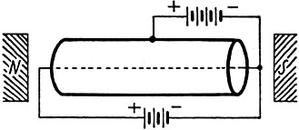
Fig. 4 - Magnetron oscillator, basic circuit.
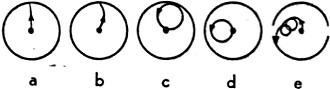
Fig. 5 - Electron paths in a magnetron tube.
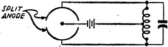
Fig. 6 - A magnetron of the split-anode type.
It has been shown theoretically how D.C. energy can be converted into A.C. energy.
Since the requirement for sustaining oscillations is that more energy be given to
the tuned circuit than is taken from it, a tuned circuit may be connected to this
triode between the grid and plate. Oscillations down to about ten centimeters wave
length may be obtained, but generally the efficiency is very low, and the maximum
power output is about 10 watts. Figure 3 shows a circuit of the type described.
Similar oscillator circuits may be obtained by connecting the tuned circuit between
the grid and cathode or the plate and cathode. In constructing this circuit the
external circuit should be a Lecher-wire system plus the other components shown
in the circuit diagram. This makes it very simple for the experimenter, as the only
component that he needs that he cannot easily construct is the tube. In fact, the
B-K circuits are the only ones he can work with at present. Fairly high frequencies
can be obtained with certain types of standard triodes having cylindrical grids
and plates, in purely experimental circuits where power output is not a consideration.
Other microwave circuit depend on special tubes which will not be obtainable by
the civilian experimenter for some time.
As the condenser shown in Figure 3 is moved along the two parallel wires from
the tube, the wave length of the oscillations will slowly increase, suddenly drop,
then increase again. This is known as the Gill-Morell effect, and shows that the
external circuit obviously influences the oscillations inside the tube.
Probably the most important type of tube in present-day microwave applications
is the magnetron. Basically, the magnetron consists of a plate in the form or a
cylinder, a filament that runs axially through the cylindrical plate, and the poles
or a strong magnet so placed that the lines of magnetic force also run axially through
the cylinder, as shown in Figure 4. With no magnetic field, the electrons travel
from the filament to the plate without interference, but when a magnetic field is
applied, these paths become curved, increasing in curvature with the increasing
magnetic strength, until a cutoff point is reached. At this point, the electrons
just graze the cylinder, and return to the cathode. With a still greater increase
in magnetic field, the electrons travel a much shorter path, and miss the cathode
completely.
At the cutoff point, the plate current drops to practically zero, and past cutoff
point, it does become zero. Typical electron paths are shown in Fig. 5. Most
often in practical applications the plate is split into two or more segments as
shown in Fig. 6. In this type of circuit the tuned circuit between the two
magnetron sections interacts on the electrons in such a manner that they move spirally,
as shown in Fig. 5-e. There are several methods of producing oscillations with
the magnetrons, but since the field is so large, only the transit-time method will
be considered here. It is the method most nearly like that previously described
for the Barkhausen-Kurz oscillator. Assume that we have a split-anode magnetron,
as in Fig. 6, with an A.C. voltage applied between the segments.
Those electrons which leave the cathode and strike the plate give up energy to
the A.C. source applied to it. Those which return to the cathode give up energy
to it which was extracted from the A.C. plate source. In order that the oscillations
be sustained, it is necessary that more energy be given up to the A.C. source than
taken from it, as this A.C. source is actually the tuned circuit. Electron velocities
are increased and decreased by the A.C. source in the magnetron in the same manner
as in the B-K circuit, and the energy extractions and deliveries are the same.
Therefore, it may be seen that the ideal situation is for the electron to make
several oscillations and eventually land on the plate. This is accomplished in two
manners. The first is to tilt the magnetic field at an angle not exceeding 10 degrees.
This gives the electron a helical path, ending on the plate. The other method is
to put end plates on the cylinder, so that the effect is the same.
Magnetrons have many applications in the microwave field, and the developments
have gone much further than security regulations will permit discussion of. They
are used to produce the shortest sustained oscillations yet attained, with wave
lengths down to less than 1 centimeter in length.
End of Part II
*Hq. AAF. Office Asst. Chief of Air Staff, Training Aids Division.
Posted December 15, 2022
(updated from original post on 9/24/2014)
|