|
October 1945 Radio-Craft
 [Table of Contents] [Table of Contents]
Wax nostalgic about and learn from the history of early electronics.
See articles from Radio-Craft,
published 1929 - 1953. All copyrights are hereby acknowledged.
|
Major Eugene Skinner (a mere
Captain when the previous two parts were written) wrote many articles about radar
and microwave technology for Radio-Craft magazine. In 1945 he provided
a three-part series entitled "Microwaves." This third part focuses on antennas and
radiators, including waveguides and feedhorns. The discussion is high level covering
the basic operation of basic circuit elements, so it is excellent fodder for people
new to the field - hobbyists, students, technicians, and engineers. The previous
two parts are also available if you want to start at the beginning.
See Microwaves Part I,
Part II,
Part III, and
Klystron: Tube of the Future.
Microwaves: Part III - Antennas and Radiators
Major Eugene E. Skinner was born on a farm near Kaufman, Texas,
in 1919. He constructed the first television transmitter and receiver in the American
Southwest while doing post-graduate work at Dallas Technical High School. After
a course at the American Television Institute in Chicago, he entered the University
of Texas, from which he graduated as Bachelor of Science in Electrical Engineering
in 1941. He is now on leave to the armed services from the Commonwealth Edison Co.
of Chicago.
Major Skinner was one of the first Radar officers in the Army
Air Forces, having been assigned to the RAF and RCAF when the United States entered
the war. He graduated from the RAF radar school at Prestwick, Scotland, in 1942,
and later from the Army Air Force School at Boca Raton Field, Florida. He has engaged
in development, maintenance, operation, installation, instruction and staff work
with the AAF, and is now assigned to Headquarters, Army Air Forces, Special Projects
Branch.
By Major Eugene E. Skinner*
Microwave systems pose relatively simple antenna problems. They can use practically
any type of antenna that has been developed for any other system, but in a much
less weighty and cumbersome form. Applying the same principles, but due to the extreme
shortness of wave length, a microwave system can use a few feet of cable and a few
inches of metal rod to do what, for a long-wave system, would require a tremendous
array, possibly covering several acres. In addition to the previous types of antennas,
two additional types designed especially for microwave applications may be used.
One is the horn, which looks much like a funnel. The stem is a hollow waveguide,
and the bowl flares gradually from this into an opening that is several wave-lengths
across.
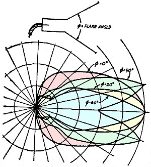
Fig. 1 - Radiation angles for horns of different flare angles,
all other factors being equal.
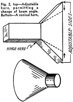
Fig. 2 - Adjustable horn, permitting a change of beam angle (top).
A conical horn (bottom).
Construction problems in an antenna like this require a greater knowledge of
sheet-metal work than of anything else. If a highly directional beam is to be broadcast
or received using the horn type antenna, an exponential horn may be used, but for
most purposes, a simple type similar to that shown in Fig. 1 is satisfactory. In
this type, the directivity can be controlled by varying the flare angle. Using this
method, the beam is wide at 0° (straight cylinder with no flare), narrows considerably
at 20°, and becomes sufficiently narrow for most purposes at 60°. At 90°,
however, the pattern is very wide and somewhat erratic. For the ham, it is suggested
that an adjustable horn like that of Fig. 2 would be simple to construct. One fixed
at 60° would be yet simpler, and probably would be very satisfactory, since
beams or radar-type sharpness are not required.
Probably the most used form of microwave antenna for present-day applications
is a short dipole, together with a parabolic reflector of metal, which looks like
a large wash-bowl, but which is very accurately designed. The more accurate the
reflector, the more efficient the antenna, but an amateur with knowledge of sheet-metal
work and simple mathematics involving parabolas can easily construct a fairly accurate
and very simple reflector. The antenna is placed at the focal point of the reflector,
and were it of infinitely small size, a sharp beam depending on the size of the
reflector could be formed. However, the dipole does have a definite length, depending
upon the frequency used. Since this length becomes shorter as the wave length is
decreased, the beam becomes sharper until only a few degrees wide.
Actually an application of this sort shows the similarity of microwaves to light
very well, for if the reflector were a mirror, and the antenna were a source of
light, the light would be beamed in the same manner as the microwaves. A sealed-beam
automobile headlight is a good example of this.
This type of antenna is practically usable only at microwave frequencies due
to the, physical dimensions involved. Using a focusing type of antenna makes it
unnecessary to have an excess of power to allow for waste, since most of the power
is condensed into the beam. Of course, an antenna sends energy away from the reflector
as well as into it, causing a waste of energy by scattering. This is usually eliminated
by placing a semi-cylindrical cup in the position shown in Fig. 3, which forces
all the energy into the reflector for forming into the beam.
A focusing effect similar to that given by the solid metal parabolic reflector,
but not as efficient, is possible by placing parasitic wires in position to form
a parabolic curve, and a great variety of shapes and patterns are possible by various
arrangements of reflectors, directors, and corner reflectors. These are much too
numerous to discuss individually.
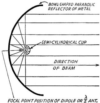
Fig. 3 - Antenna with parabolic reflector.
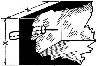
Fig. 4 - Square waveguide, fed from the end.

Fig. 5 - A square waveguide with lateral feed.
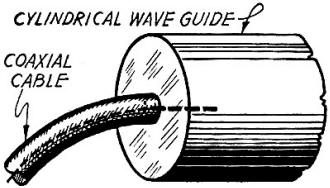
Fig. 6 - Cylindrical waveguide with end feed.
At microwave frequencies, coaxial conductors are not satisfactory for transmission
of energy from one spot to another except for very short distances, therefore another
type of conductor is used. This is the waveguide, which is made in a wide variety
of forms.
If a radio wave is projected from the earth into the atmosphere, it strikes the
ionosphere and is reflected back to earth, where it is reflected again to the ionosphere.
This reflection between these two layers continues until the wave is dissipated
which might occur in only one reflection, or several. Similarly, by placing two
metal plates close together with an antenna between them this radiation will be
reflected between them several times at angles depending upon their distance apart,
until it is reflected out at the edges of the plates. If the two plates are placed
with another pair of plates, so that they form a square or rectangular pipe, and
one end sealed, with the antenna mounted on it in the proper position, all the energy
is confined within the pipe, and may escape only out the one open end. This waveguide
may be square, rectangular, circular, or even elliptical in cross section. Generally
speaking the opening must be equal to or greater than the wave length in order to
permit the guiding of waves, making it extremely impractical for use with longer
wave lengths. With this as a rough guide, it is readily seen that there is a maximum
wave length for any given waveguide, and for greater wave lengths the, guide acts
as a high-pass filter. However, any wave length shorter than this critical value
will pass through very readily. More exact formulas may be found in any good text
on microwaves, together with elaborate discussions of the electrostatic and electromagnetic
fields within the guides. Discussions of this type are very lengthy and are not
of sufficient interest to the average reader to warrant discussion here. Figures
4, 5 and 6 show typical waveguides of the square, rectangular, and circular types.
Figure 4 shows a square waveguide with a stub antenna in the form of the end of
the center wire of a coaxial cable projected into the end of the waveguide.
Another method of exciting the waveguide is shown in Fig. 5, which shows the
same type input, except that it is into the side of a rectangular type waveguide,
and near the end. It is the usual thing for this type to be injected into the wider
side. End type injection is commonly used with cylindrical waveguides.
More elaborate inputs may be used, such as pairs of stubs properly placed, or
dipoles, or with even more elements, but only the simplest are shown here, as they
are adequate.
Coupling to the Waveguide
To take energy from the waveguide, if an electrode is used, it must be of the
same type as that used at the input, and must be oriented in the same direction.
Since this is true, it is actually possible to use several types of waves within
the same waveguide at the same time, and sort or filter them out by the various
input and output methods! Waveguides may be terminated in the electromagnetic horns
previously described. If coaxial cables and an electromagnetic horn are to be connected,
a short waveguide is used as coupling.
For experimental purposes, a slot may be left, through which a probe connected
to a detector arrangement may be placed in order to determine the field distribution
within the waveguide.
Waveguides can be constructed by the amateur very easily from sheet metal, making
possible a wide range of experimentation with very little investment. As a matter
of fact, the whole microwave field is open to the amateur with relatively low outlay.
The only commercially manufactured items which are necessary are the basic oscillator
tubes and some cable. A good power supply, waveguides, and antennas can be made
by the ham - and nothing more is needed, other than the shop facilities that practically
all amateurs have readily available. Several excellent books are available on microwaves
and ultra-high-frequencies, and it is recommended that those who wish to pursue
the subject of Microwaves further investigate these.
References
1. Introduction to Microwaves, by Simon Ramo (McGraw-Hill).
2. Ultra-High Frequency Techniques, by Brainerd, Koehler, Reich, & Woodruff
(D. Van Nostrand).
3. Basic Radio, by Hoag (D. Nostrand).
4. UHF Radio Simplified, by Milton S. Kiver (D. Van Nostrand).
6. Radio at Ultra-High Frequencies (RCA Institutes Technical Press).
6. Klystron Technical Manual (Sperry Gyroscope Company).
* Hq. AAF, Office Asst. Chief of Air Staff, Training Aids Division.
Posted August 11, 2021
|


