|
October 1944 Radio-Craft
 [Table
of Contents] [Table
of Contents]
Wax nostalgic about and learn from the history of early electronics.
See articles from Radio-Craft,
published 1929 - 1953. All copyrights are hereby acknowledged.
|
So much time has passed since
an average home garage mechanic could service his car or truck with standard tools
- combination wrenches, screwdrivers, socket sets, timing light, and a multimeter
- that asking "remember when?" is passé. That era pretty much ended in the late
1980s as computerized cars were becoming the industry norm. A good percentage of
people nowadays have never and will never service their own vehicles. In the mid
1940s, the electronics world was lamenting a similar situation with diminishing
ability to build and modify electronic components like coils and stacked plate capacitors
because of the increasingly higher frequencies being used in communications
(way up into the UHF band!). This article introduces
the klystron tube, having been around for less than a decade at the time, as being
one of the culprits that was enabling the disturbing trend ;-) . A layman's introduction
to the physics behind its operation is provided. Those guys thought they had it
bad, but knew nothing of the reduction of serviceability of electronics circuits
and components compared with our present day multi-layered printed circuit boards
stuffed to the gills with condiment-size surface mount components.
See Microwaves
Part I, Part
II, Part III,
and Klystron: Tube of the
Future.
The Klystron Will Fill Many Important Post-War U.H.F. Jobs

Fig. 1 - Evolution of a resonant-cavity circuit from the
coil-condenser combination may be traced with the help of this diagram.

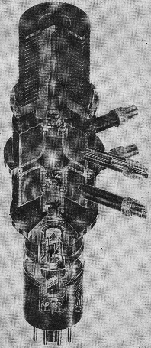
Cut-away photo of a typical Klystron.
All Illustrations Courtesy Sperry Gyroscope Co.
By Capt. Eugene E. Skinner Hq. A.A.F. Training Aids Division
The new fields of radio that have been, developed in recent years have so changed
some radio components that it is now impossible for the amateur to wind a coil,
change the number and size of the plates on a condenser, and follow the latest developments.
Instead, as frequencies become higher, special, critical components are required.
Examples of these are found in the resonant circuits and tubes.
For the ordinary range of frequencies with which radio technicians and amateurs
were concerned a few years ago, a resonant circuit could be designed to fit any
frequency or band of frequencies by changing the number of turns on a coil and the
size of the condensers, or by changing crystals. With an increase in frequency,
fewer turns in the coils and fewer condenser plates are used. As a very high range
of frequencies is reached, a single small turn of wire connecting two condenser
plates must be used and crystals become so thin as to be useless. Any further variation
along conventional lines is very difficult. New methods must be adopted.
In addition to the problems offered by these lumped circuit constants, as inductance
of turns of coils and capacitance of plates or condensers are called, the problems
of the vacuum tubes themselves become evident. These problems, caused by characteristics
which were not bothersome in ordinary tubes at lower frequencies, become of major
importance in the ultra-high-frequencies. In these ranges, such small quantities
of capacitance and inductance are needed that the capacitance between the electrodes
of the tubes and the inductance of the loops formed by the electrical circuits through
which the electrons flow in the tubes are of relatively large value. In addition
to this, the electrodes are of such size distance apart, and relative position,
that the time required for the electrons to travel through the tube becomes an appreciable
part of a cycle. Finally a frequency is reached for each type of tube at which the
starting and maintenance of steady oscillations becomes impossible. This feature
is compensated for by the construction of smaller tubes of the "acorn" and other
types, but the difficulties still exist above the ultra-high-frequencies, for eventually
the point is reached at which the tubes are necessarily so small and possess such
little power capacity as to be impractical.
One method of solving both these problems at the same time was devised by Russell
and Sigurd Varian and W. W. Hansen at Stanford University in 1937, by the invention
of "Klystron"* tubes. This type of tube embodies the principle of modulating the
velocity of the electrons as they flow through it and which has at least a portion
and possibly all of the oscillating circuit components included as integral parts
of the tube.
The most important component of the Klystron is the resonant cavity. It is an
outgrowth of the application of the lumped circuit constants in resonant circuits.
When the point is reached at which a single small loop and a pair of condenser plates
will no longer serve for the extremely high frequency desired, a method must be
devised to apply the same principles in a different form. To decrease the inductance
beyond that of a single loop, the principle that loops in parallel have less inductance
than one loop is applied. Therefore, coil loops are placed between the same pair
of condenser plates, until an infinite number of them have been added. See Fig.
1. The result is a doughnut-shaped ring slotted within the hole at the shortest
diameter, with two plates placed parallel to the axis of the doughnut, one at each
edge of the slot, so that it appears to a casual observer to be only a solid doughnut
shaped object with a short plug in the center. If laid flat and cut a one would
cut a pie, the cut edge would be like the outline of a dumbbell.
As the frequency is increased, this doughnut becomes smaller. In most Klystron
tubes two of these resonant cavities are used, one as the "buncher" and one as the
"catcher." It is obvious that an electron stream cannot pass through the solid plates
'in-the centers of these cavities. These plates are therefore replaced by meshes
or grids. In actual applications, the cavities are not always tubular doughnut in
shape but more often have distorted variations.
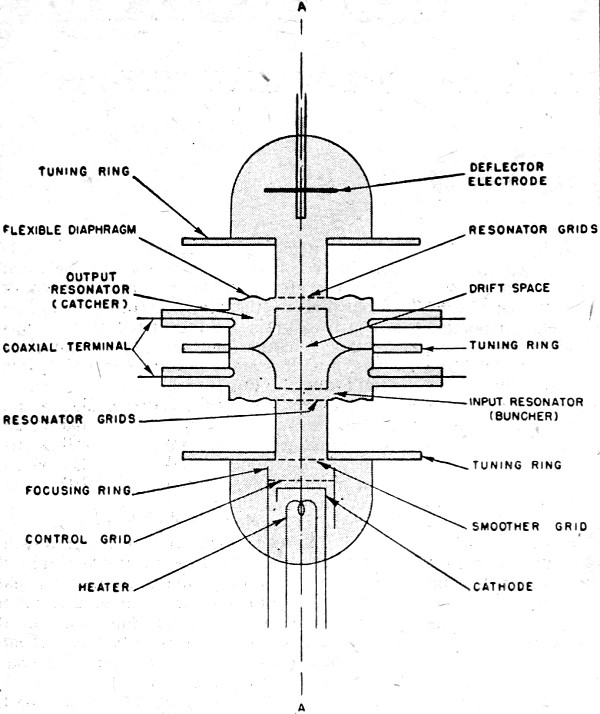
The action of the tube may be understood by referring to Fig. 2. A stream
of electrons is beamed by a cathode through focusing electrodes and an accelerator
grid toward the pair of bundler grids through which the stream must pass. The cathode
and focusing electrodes have applied to them a high negative voltage with respect
to the rest of the tube, which is grounded on the positive side. Voltage must necessarily
be well regulated as fluctuations will affect the frequency of the tube. The buncher
grids and their associated resonant cavity are excited by a radio frequency source
in such a manner that as one is positively charged, the other is negatively charged
as in coil-and-condenser action. These grids have between them, therefore, an electrostatic
field which is parallel to the flow of electrons. The strength of this field is
such that it appreciably changes the velocity of the electrons, but does not do
so to the point that it will stop the flow completely at any time. As an electron
comes into the field, assume that it enters such a portion of the cycle as to cause
it to speed up. As the radio frequency excitation passes through the zero point
of the cycle, the speed of the electron is not affected. Then, as the second half
of the cycle is applied, or the charges are reversed, the electrostatic field opposes
the flow of the electron, slowing it down. Now it can be seen that as the excitation
passes through several cycles, those electrons which have been slowed down during
a cycle are overtaken by those whose speeds were not affected, and both groups are
overtaken by those electrons which were sped up, causing a bunching of the electrons,
at a point past the "buncher" grids.

Fig. 2 - Schematic view of the Klystron.
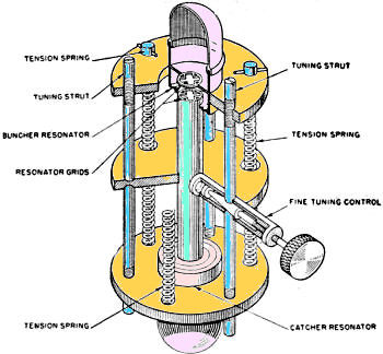
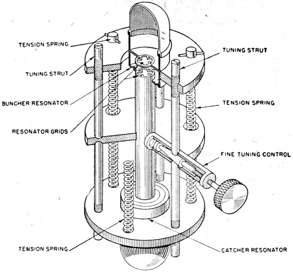
Fig. 3 - How the tube is tuned. Coarse adjustments are made
with the three large struts, fine tuning by varying one against the other two.
A second pair of grids, known as the "catcher" grids, is placed in such a position
that the bunched electrons pass through them at the rate of one bunch per cycle.
It is assumed that the first of the grids is in the negative half cycle of an oscillation.
As the electrons approach the first of these two grids, which are part of a tuned
circuit, the negative charges in the electrons induce a positive charge on the first
grid in a condenser-like action, then pass on toward the second grid. The original
negative charge on the first grid has a slowing-down effect on the electrons, and
as the energy of motion cannot be lost by the electrons without being gained elsewhere,
this loss of electrons induces energy in the tuned circuit.
The change of charge supports the oscillation in the tuned circuit, and by the
time the bunch of electrons has reached the second catcher grid, the oscillations
have changed the charge on it so that it is then negative. This negative charge,
again in opposition to the charge of the electrons still further decreases the velocity
of the electrons, and, as before, this loss of energy by the electrons induces energy
in this tuned circuit. After the electrons have passed the catcher grids, they are
picked up on a collector plate.
It can readily be seen that the energy considerations are very important. It
has been shown how energy is taken from the catcher grids while none is supplied
from sources other than the electron stream. In , the buncher, it is necessary to
supply a source of energy to provide for the bunching, but as some of the electrons
are speeded up, taking up energy from the buncher, so are some of them slowed down,
giving up an almost equal amount of energy to the buncher. The overall result is
that there is a very little additional energy needed. A short coaxial cable feedback
from the catcher to the buncher provides the necessary source of radio frequency
oscillations and energy. The excess energy from the catcher is the output of the
tube and is also taken from the resonant cavity by means of a coaxial cable. Output
and the feedback is accomplished by means of one-turn loops which are formed by
the central conductor of the coaxial cables, which enter the hollow "doughnut,"
form a loop, and are grounded at the end. A part of the magnetic flux of the resonant
cavities which exists within the hollow doughnut cavities, also passes through this
loop, giving an inductive coupling which is the equivalent of an air-cored transformer.
The Klystron tubes are very versatile and have many applications. In addition
to their electrical capabilities, they are reasonably rugged, lending great value
under far-from-ideal combat conditions. As the frequencies increase, the tubes become
smaller, the wave lengths being the controlling factor of practically all the physical
dimensions. The general design is such as to provide satisfactorily for the necessary
dissipation of heat.
Tuning the Klystrons may be accomplished by several different methods, depending
upon their physical construction. If a tube is so constructed that the cavity is
sealed within it, provision may be made whereby tuning can be accomplished by changing
the spacing between the grids. Most Sperry Klystrons utilize a screw-type arrangement
by which the spacing between the grids can be varied, made possible by having the
grids mounted on a diaphragm which can be flexed by the screw control. See Fig. 3.
This spacing is the most critical dimension as far as frequency is concerned.
If the cavity is outside the tube, tuning may be accomplished by screwing plugs
into the cavity, effectively changing its volume. Several other methods of varying
the dimensions of the resonant cavity or the flux inside it may be used, as well
as variation of the applied voltage.
When no method of feedback is used with the Klystron tube, but a separate oscillation
is used in the buncher, the tube is being applied in its simplest form as an amplifier.
Since the beam of electrons gives off a great deal more energy than it absorbs,
it is therefore a power amplifier (equivalent of a Class C type) and may also be
used as a voltage amplifier for small radio-frequency voltages.
All that is necessary to convert such an amplifier into an oscillator is a method
of feedback so as to sustain oscillations, and this is accomplished by means of
the coaxial feedback coupling previously described. The Klystron is generally as
efficient as any other type of ultra-high-frequency oscillator. While theory indicated
that efficiencies of 58% are possible, in actual practice they are considerably
less.
It is very improbable that electrons would be bunched in such a manner as to
produce a pure sine wave. The wave produced is actually composed of a large number
of harmonics. This being the case, it is only natural that the Klystron tube should
find application as a frequency multiplier. In order to accomplish this, it is necessary
that the relative phase of the two resonant cavities be such that bunches of electrons
hit the catcher at a time which will cause the oscillations to build up, and the
catcher cavity must be designed for the desired harmonic frequency.
Unfortunately a great many of the most important applications of the Klystron
tubes cannot be discussed. In the meantime, more and more applications are becoming
apparent daily in the fields opened by the discovery of this important electronic
device.
One thing that the war, or rather, the peace which follows it, should be able
to do for radio is to clean up and set in order the wavebands assigned to broadcasting.
You remember the pre-war semi-chaos which conferences, plans and much hard work
on the part of the U.I.R. (Radio International Union) had failed to straighten out?
The end of the war will furnish a glorious opportunity of setting all this to rights
and of forming a governing body for broadcasting in Europe as enlightened and as
powerful as the Federal Communications Commission in the United States. One thing
that most of us would like to see is a return to the original 10-kilocycle separation
between stations - the 9-Kc. separation in operation when the war broke out was
not sufficient to ensure decent quality or to prevent heterodynes.-(Wireless World,
July 1944)
*Trade Mark Registered by Sperry Gyroscope Co.
Posted April 14, 2021
(updated from original post on 11/12/2014)
|