|
Gain for an antenna is expressed in decibels relative to an isotropic radiator
(point source that radiates equally in every direction). Physical attributes of
an antenna, in conjunction with the operating frequency, results in constructive
and destructive interference patterns being set up a points distant from the antenna.
Where the fields add constructively a positive gain is experienced, and where fields
add destructively a negative gain is experienced (relative to isotropic). These
drawings and parameters were derived from the
EW and Radar Systems
Engineering Handbook.
| Narrowband
BW = (fU - fL) / fC |
| 5 |
1.05:1 |
40 |
1.50:1 |
| 10 |
1.11:1 |
50 |
1.67:1 |
| 20 |
1.22:1 |
60 |
1.85:1 |
| 30 |
1.35:1 |
|
|
|
| Broadband BW = fU /
fL |
| 67 |
2:1 |
150 |
7:1 |
| 100 |
3:1 |
160 |
9:1 |
| 120 |
4:1 |
163 |
10:1 |
| 133 |
5:1 |
|
|
|
 |
 |
| G=20 log (D/λ) + 10 log (a) + 9.938 dB D= diameter a
= illumination factor (typ = 0.6) λ = wavelength Keep dimensional
units similar; i.e., meters, inches. |
Gain (typ): 10 to 60 dB Bandwidth:
33% (1.4:1) Frequency Limit: Lower
- 400 MHz
(due to size) Upper - 13+ GHz Polarization:
Polarization of feed Half-Power Beamwidth:
1 to 10º |
 |
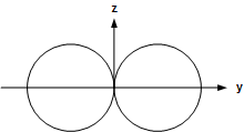
 Elevation Pattern Azimuth Pattern |
| Gain (typ): 2 dB Bandwidth: 10% (1.1:1)
Frequency Limit: Lower: none Upper:
8 GHz
(due to size) |
Polarization: Linear
(vertical as shown) Half-Power BW (typ):
80º x 360º Notes: Pattern and lobing change significantly
with L/f. Used as gain reference for f < 2 GHz. |
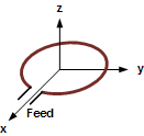
 Configuration |
 Elevation Pattern Azimuth Pattern |
| Gain (typ): 2 to 6 dB Bandwidth: 10%
(1.1:1) Frequency Limit: Lower: none Upper:
none |
Polarization: Linear
(vertical as shown) Half-Power BW (typ): 45º
x 360º Notes: Polarization changes to horizontal if antenna
is rotated to horizontal. |
 |
 Elevation Pattern
 Azimuth Pattern |
|
Polarization: Linear
Half-Power BW (typ): 60º x 80º
Gain (typ): 6 to 8 dB
Bandwidth: 163% or 10:1
|
Frequency Limit: Lower: 3 MHz
Upper: 18 GHz
Remarks: This array may be formed with many shapes including
dipoles or toothed arrays.
|
 |
 Elevation Pattern
 Azimuth Pattern |
| Gain (typ): 5 to 15 dB
Bandwidth: 5% (1.05:1) Frequency Limit:
Lower: 50 MHz Upper: 2 GHz |
Polarization: Linear
(horizontal as shown) Half-Power BW)
(typ): 50º x 50º |
 |
 Elevation Pattern
 Azimuth Pattern |
| Gain (typ): -2 to 2 dB Bandwidth: 10%
(1.1:1) Frequency Limit: Lower: 50
MHz Upper: 1 GHz |
Polarization: Linear
(horizontal as shown) Half-Power BW
(typ): 80º x 360º |
 |
 Elevation Pattern
 Azimuth Pattern |
| Gain (typ): 1 to 3 dB Bandwidth: 10%
(1.1:1) Frequency Limit: Lower: 50
MHz Upper: 1 GHz |
Polarization: Linear
(horizontal as shown) Half-Power BW
(typ): 100º x 360º |
 |
 Elevation & Azimuth Pattern
|
| Polarization: Linear
(vertical as shown) Half-Power BW (typ):
60 deg x 60 deg Gain (typ): 2 to 7 dB Bandwidth:
"Broadband" |
Frequency Limit: Lower: 3 MHz
Upper: 500 MHz
(practical limit) Remarks: 24 kHz versions are known
to exist. Terminations may be used to reduce back lobes. |
 |
 3 dB beamwidth 56 * λ / h Elevation Pattern
 3 dB beamwidth 70 * λ / w Azimuth Pattern |
| Gain (typ): 5 to 20 dB
Bandwidth: 120% (4:1) - ridged 67%
(2:1) - non-ridged Frequency Limit:
Lower - 50 MHz Upper - 40 GHz |
Polarization: Linear
(vertical as shown) Half-Power BW (typ): 40º
x 40º |
Related Pages on RF Cafe -
Antenna Patterns -
Antennas - Hardware & Controls -
Antennas - Manufacturers & Services -
Test Equipment & Calibration - Antenna Measurement
-
Antenna Introduction / Basics -
Antenna
Radiation Patterns -
Antenna
Near Field - Near-Field
/ Far-Field Transition Distance -
Intro
to Wave Propagation, Transmission Lines, Antennas -
Antenna, Electromagnetics & X-mission
Line Simulators -
Satellite Communications - Antennas -
Short Wire Antennas
|


