|
||||||||||||||||||||||||||||||||||||||||||||||||||||||||||||||||||||||||||||||||||||||||||||||||||||||||||||||||||||||||||||||||||||||||||||||||||||||||||||
 |
||||||||||||||||||||||||||||||||||||||||||||||||||||||||||||||||||||||||||||||||||||||||||||||||||||||||||||||||||||||||||||||||||||||||||||||||||||||||||||
Bessel Filter Lowpass Prototype Element Values |
||||||||||||||||||||||||||||||||||||||||||||||||||||||||||||||||||||||||||||||||||||||||||||||||||||||||||||||||||||||||||||||||||||||||||||||||||||||||||||
|
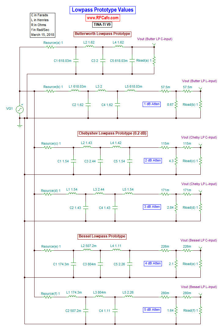
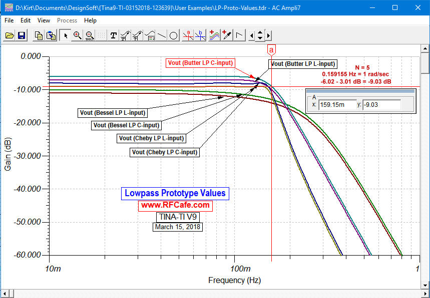
Simulations of Normalized and Denormalized LP, HP, BP, and BS Filters
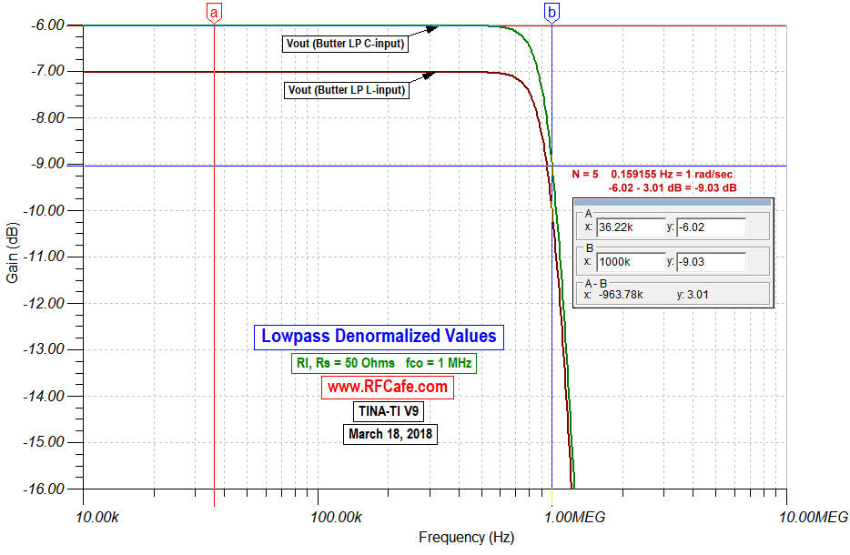
Lowpass Filters (above)
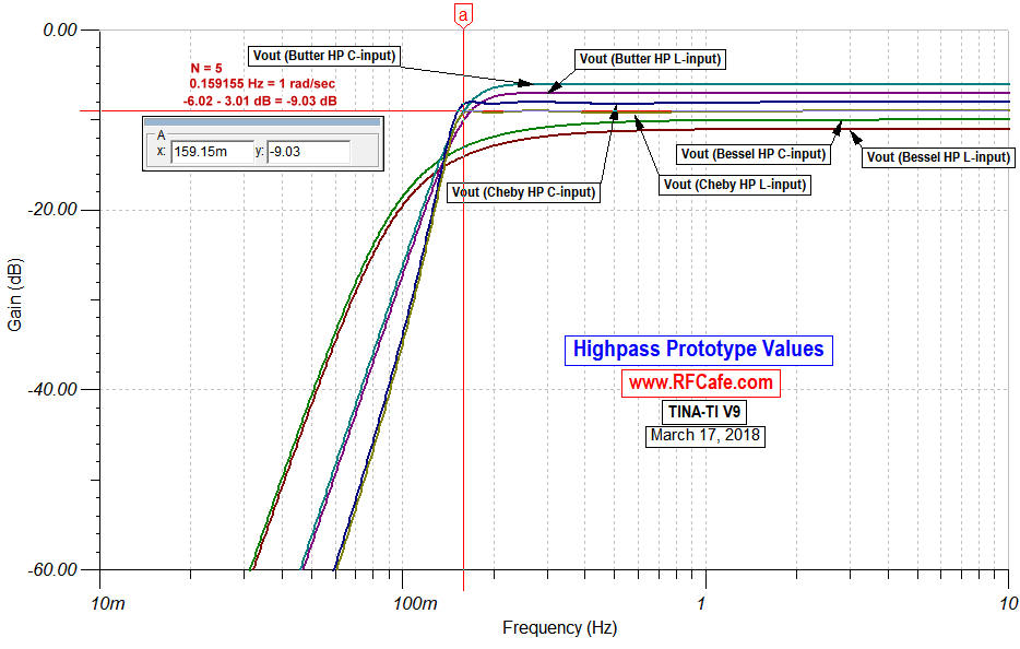
Highpass Filters (above)
Bandpass and Bandstop Filters (above) A Bessel filter is a filter whose impulse response is a Bessel function. Bessel filters are designed to give maximally flat group delay and maximally linear phase change across the band and into the transition region. They are very close to Gaussian type filters. The table below lists prototype element values for the normalized lowpass function, which assumes a cutoff frequency of 1 rad/sec and source and load impedances of 1 Ω. Either an input capacitor (top reference line in table) or an input inductor (bottom line in table) can be used. Convert values to other cutoff frequencies, impedances, and to highpass, bandpass or bandstop using denormalization equations.
Related Pages on RF Cafe - Butterworth Filter Equations for Magnitude, Phase, and Group Delay - Chebyshev Filter Equations for Magnitude, Phase, and Group Delay - Butterworth Lowpass Filter Gain, Phase, and Group Delay Equations - Butterworth Highpass, Bandpass, & Bandstop Filter Gain, Phase, and Group Delay Equations - How to Use Filter Equations in a Spreadsheet - Filter Equivalent Noise Bandwidth - Filter Prototype Denormalization - Bessel Filter Prototype Element Values - Butterworth Lowpass Filter Poles - Butterworth Filter Prototype Element Values - Chebyshev Lowpass Filter Poles - Chebyshev Filter Prototype Element Values - Monolithic Ceramic Block Combline Bandpass Filters Design - Coupled Microstrip Filters: Simple Methodologies for Improved Characteristics |
||||||||||||||||||||||||||||||||||||||||||||||||||||||||||||||||||||||||||||||||||||||||||||||||||||||||||||||||||||||||||||||||||||||||||||||||||||||||||||
 |
||||||||||||||||||||||||||||||||||||||||||||||||||||||||||||||||||||||||||||||||||||||||||||||||||||||||||||||||||||||||||||||||||||||||||||||||||||||||||||
|
||||||||||||||||||||||||||||||||||||||||||||||||||||||||||||||||||||||||||||||||||||||||||||||||||||||||||||||||||||||||||||||||||||||||||||||||||||||||||||


|
||||||||||||||||||||||||||||||||||||


