Module 8 - Introduction to Amplifiers
Pages i,
1-1,
1-11,
1-21,
1-31,
2-1,
2-11,
2-21,
2-31,
3-1,
3-11,
3-21,
3-31,
3-41,
3-51,
3-61,
AI-1,
Index
| - |
Matter, Energy,
and Direct Current |
| - |
Alternating Current and Transformers |
| - |
Circuit Protection, Control, and Measurement |
| - |
Electrical Conductors, Wiring Techniques,
and Schematic Reading |
| - |
Generators and Motors |
| - |
Electronic Emission, Tubes, and Power Supplies |
| - |
Solid-State Devices and Power Supplies |
| - |
Amplifiers |
| - |
Wave-Generation and Wave-Shaping Circuits |
| - |
Wave Propagation, Transmission Lines, and
Antennas |
| - |
Microwave Principles |
| - |
Modulation Principles |
| - |
Introduction to Number Systems and Logic Circuits |
| - |
- Introduction to Microelectronics |
| - |
Principles of Synchros, Servos, and Gyros |
| - |
Introduction to Test Equipment |
| - |
Radio-Frequency Communications Principles |
| - |
Radar Principles |
| - |
The Technician's Handbook, Master Glossary |
| - |
Test Methods and Practices |
| - |
Introduction to Digital Computers |
| - |
Magnetic Recording |
| - |
Introduction to Fiber Optics |
| Note: Navy Electricity and Electronics Training
Series (NEETS) content is U.S. Navy property in the public domain. |
An adder circuit is not restricted to two inputs.
By adding resistors in parallel to the input terminals, any number of inputs can
be used. The adder circuit will always produce an output that is equal to the sum
of the input signals but opposite in polarity. Figure 3-22 shows a five-input adder
circuit with voltages and currents indicated.
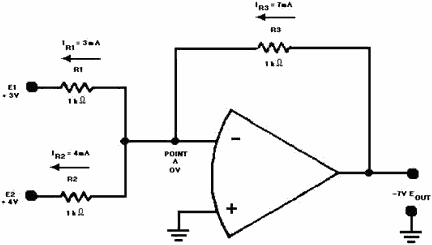
Figure 3-21. - Current and voltage in a two-input adder.
3-31
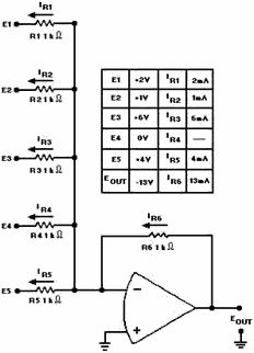
Figure 3-22. - Five-input adder.
The previous circuits have been adders, but there are other types of summing
amplifiers. a summing amplifier can be designed to amplify the results of adding
the input signals. This type of circuit actually multiplies the sum of the inputs
by the gain of the circuit.
Mathematically (for a three-input circuit):

If the circuit gain is -10:

The gain of the circuit is determined by the ratio between the feedback resistor
and the input resistors. To change figure 3-20 to a summing amplifier with a gain
of -10, you would replace the feedback resistor (R3) with a 10-kilohm resistor.
This new circuit is shown in figure 3-23.
3-32
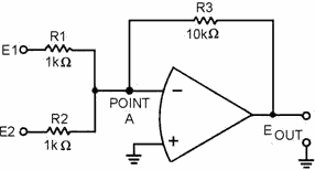
Figure 3-23. - Summing amplifier.
If this circuit is designed correctly and the input voltages (E1 and E2) are
+2 volts and +3 volts, respectively, the output voltage (Eout) should be:

To see if this output (-50 V) is what the circuit will produce with the inputs
given above, start by calculating the currents through the input resistors, R1 and
R2 (remember that point a is at virtual ground):

Next, calculate the current through the feedback resistor (R3):
3-33

(The minus sign indicates current flow from left to right.)
Finally, calculate the voltage dropped across R3 (which must equal the output
voltage):

As you can see, this circuit performs the function of adding the inputs together
and multiplying the result by the gain of the circuit.
One final type of summing amplifier is the SCALING Amplifier. This circuit multiplies
each input by a factor (the factor is determined by circuit design) and then adds
these values together. The factor that is used to multiply each input is determined
by the ratio of the feedback resistor to the input resistor. For example, you could
design a circuit that would produce the following output from three inputs (E1,
E2, E3):

Using input resistors R1 for input number one (E1), R2 for input number two (E2),
R3 for input number three (E3), and R4 for the feedback resistor, you could calculate
the values for the resistors:

Any resistors that will provide the ratios shown above could be used. If the
feedback resistor (R4) is a 12-kilohm resistor, the values of the other resistors
would be:
3-34

Figure 3-24 is the schematic diagram of a scaling amplifier with the values calculated
above.
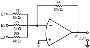
Figure 3-24. - Scaling amplifier.
To see if the circuit will produce the desired output, calculate the currents
and voltages as done for the previous circuits.
With:

the output should be:
3-35

Calculate the current for each input:
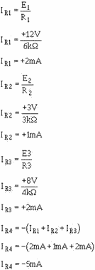
Calculate the output voltage:

3-36
You have now seen how an operational amplifier can be used in a circuit as an
adder, a summing amplifier, and a scaling amplifier.
Difference Amplifier (Subtractor)
A difference amplifier will produce an output based on the difference between
the input signals. The subtractor circuit shown in figure 3-25 will produce the
following output:
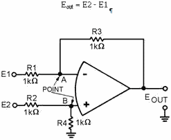
Figure 3-25. - Subtractor circuit.
Normally, difference amplifier circuits have the ratio of the inverting input
resistor to the feedback resistor equal to the ratio of the noninverting input resistors.
In other words, for figure 3-25:

and, by inverting both sides:

For ease of explanation, in the circuit shown in figure 3-25 all the resistors
have a value of 1 kilohm, but any value could be used as long as the above ratio
is true. For a subtractor circuit, the values of R1 and R3 must also be equal, and
therefore, the values of R2 and R4 must be equal. It is NOT necessary that the value
of R1 equal the value of R2.
Using figure 3-25, assume that the input signals are:

The output signal should be:
3-37
Eout = E2 - E1
Eout = (+12V) - (+3V)
Eout = +9V
To check this output, first compute the value of R2 plus R4:

With this value, compute the current through R2 (IR2):

(indicating current flow from left to right)
Next, compute the voltage drop across R2 (ER2):

Then compute the voltage at point B:

Since point B and point a will be at the same potential in an operational amplifier:

Now compute the voltage developed by R1 (ER1):

Compute the current through R1 (IR1):
3-38
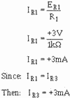
Compute the voltage developed by R3 (ER3):

Add this to the voltage at point a to compute the output voltage (Eout):

As you can see, the circuit shown in figure 3-25 functions as a subtractor. But
just as an adder is only one kind of summing amplifier, a subtractor is only one
kind of difference amplifier. a difference amplifier can amplify the difference
between two signals. For example, with two inputs (E1 and E2) and a gain of five,
a difference amplifier will produce an output signal which is:

The difference amplifier that will produce that output is shown in figure 3-26.
Notice that this circuit is the same as the subtractor shown in figure 3-25 except
for the values of R3 and R4. The gain of this difference amplifier is:
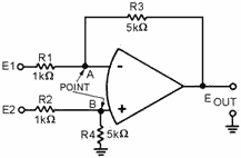
Figure 3-26. - Difference amplifier.
3-39

Then, for a difference amplifier:

With the same inputs that were used for the subtractor, (E1 = + 3 V; E2 = + 12
V) the output of the difference amplifier should be five times the output of the
subtractor (Eout = + 45 V).
Following the same steps used for the subtractor: First compute the value of
R2 plus R4:

With this value, compute the current through R2 (IR2):

Next, compute the voltage drop across R2 (ER2):

Then, compute the voltage at point B:

Since point a and point B will be at the same potential in an operational amplifier:

3-40
|


