Module 12 - Modulation Principles
Pages i,
1-1,
1-11,
1-21,
1-31,
1-41,
1-51,
1-61,
1-71,
2-1,
2-11,
2-21,
2-31,
2-41,
2-51,
2-61,
3-1,
3-11,
3-21,
3-31, AI-1, Index, Assignment 1, 2
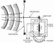
Figure 1-36. - Magnetic microphone action. When the armature is in its resting position (midway between the two poles), the magnetic flux is
established across the air gap. However, no resultant flux is established in the armature. When a compression wave
strikes the diaphragm, the armature is deflected to the right. Most of the flux continues to move in the direction
of the arrows. However, some flux now flows from the north pole of the magnet across the reduced gap at the upper
right, down through the armature, and around to the south pole of the magnet. When a rarefaction wave
occurs at the diaphragm, the armature is deflected to the left. Some flux is now directed from the north pole of
the magnet, up through the armature, through the reduced gap at the upper left, and back to the south pole. The vibrations of the diaphragm cause an alternating flux in the armature which induces an alternating voltage in
the coil. This voltage has the same waveform as that of the sound waves striking the diaphragm. The
magnetic microphone is very similar to the dynamic microphone in terms of impedance, sensitivity, and frequency
response. However, it is more resistant to vibration, shock, and rough handling than other types of microphones. Changing sound waves into electrical impulses is the first step in voice communications. It is common to all the
transmission media you will study in the remainder of this chapter. We will discuss the various types of
modulation that arc used to transfer this information to a transmission medium in the following sections. Q-26. What is a microphone? Q-27. What special electromechanical effect is the basis for carbon microphone
operation? Q-28. What is a major disadvantage of a carbon microphone?
Q-29. What property of a crystalline material is used in a crystal microphone? Q-30. What is the
difference between a dynamic microphone and a magnetic microphone? 1-41
AM Transmitter Principles In this section we will describe the methods used
to apply voice signals (intelligence) to a carrier wave by the process of amplitude modulation (AM). An AM
transmitter can be divided into two major sections according to the frequencies at which they operate,
radio-frequency (RF) and audio-frequency (AF) units. The RF unit is the section of the transmitter used to
generate the RF carrier wave. As illustrated in figure 1-37, the carrier originates in the master oscillator stage
where it is generated as a constant-amplitude, constant-frequency sine wave. The carrier is not of sufficient
amplitude and must be amplified in one or more stages before it attains the high power required by the antenna.
With the exception of the last stage, the amplifiers between the oscillator and the antenna are called
INTERMEDIATE Power AmplifierS (IPA). The final stage, which connects to the antenna, is called the FINAL Power
Amplifier (FPA). 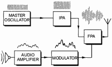
Figure 1-37. - Block diagram of an AM transmitter. The second section of the transmitter contains the audio circuitry. This section of the transmitter
takes the small signal from the microphone and increases its amplitude to the amount necessary to fully modulate
the carrier. The last audio stage is the Modulator. It applies its signal to the carrier in the final power
amplifier. In this way, intelligence is included in the radiated RF waveform. The Modulated Wave
The frequencies present in a signal can be conveniently represented by a graph of the frequency spectrum,
shown in figure 1-38. In this graph, each individual frequency is portrayed as a vertical line. The position of
the line along the horizontal axis indicates the frequency of the signal. The height of the frequency line is
proportional to the amplitude of the signal. The RF spectrum in figure 1-38 shows the frequencies present when
heterodyning occurs between frequencies of 5 and 100 kilohertz. 1-42
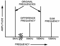
Figure 1-38. - Radio-frequency spectrum. Radiating energy at audio frequencies (discussed earlier in this chapter) is not practical. The
heterodyning principle, however, makes possible the conversion of an af signal (intelligence) to an RF signal
(with AF intelligence) which can be radiated or transmitted through space. Look again at figure 1-38. The
sum and difference frequencies are located very near the RF signal (100 kilohertz), while the audio signal (5
kilohertz) is spaced a considerable distance away. Because of this frequency separation, the audio frequency can
be easily removed by filter circuits, leaving just three radio frequencies of 95, 100, and 105 kilohertz. These
three radio frequencies are radiated through space to the receiving station. At the receiver, the process is
reversed. The frequency of 95 kilohertz, for example, is heterodyned with the frequency of 100 kilohertz and the
sum and difference frequencies are again produced. (A similar process occurs between the frequencies of 100 and
105 kilohertz.) Of the resultant frequencies (95, 100, 105, and 5 kilohertz), all are filtered out except the 5
kilohertz difference frequency. This frequency, which is identical to the original 5 kilohertz audio applied at
the transmitter, is retained and amplified. Thus, the 5 kilohertz audio tone appears to have been radiated through
space from the transmitter to the receiver. In the process just described, the 100 kilohertz frequency is referred to as the CARRIER Frequency, and
the sum and difference frequencies are referred to as SIDE FREQUENCIES. Since the sum frequency appears above the
carrier frequency, it is referred to as the Upper SIDE Frequency. The difference frequency appears below the
carrier and is referred to as the LowER SIDE Frequency. When a carrier is modulated by voice or music
signals, a large number of sum and difference frequencies are produced. All of the sum frequencies above the
carrier are spoken of collectively as the Upper SIDEBand. All the difference frequencies below the carrier, also
considered as a group, are called the LowER SIDEBand. If the carrier and the modulating signal are
constant in amplitude, the sum and difference frequencies will also be constant in amplitude. However, when the
carrier and sidebands are combined in a single impedance and viewed simultaneously with an oscilloscope, the
resultant waveform appears as shown in figure 1-39. This resultant wave is called the MODULATION ENVELOPE. The
modulation envelope has the same frequency as the carrier. However, it rises and falls in amplitude with the
continual phase shift between the carrier and sidebands. This causes these signals to first aid and then oppose
one another. These cyclic variations in the amplitude of the envelope have the same frequency as the
audio-modulating 1-43
voltage. The audio intelligence is actually contained in the spacing or difference between the carrier
and sideband frequencies. 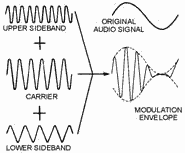
Figure 1-39. - Formation of the modulation envelope. Bandwidth of an AM WAVE. - An ideal carrier wave contains a single frequency and occupies
very little of the frequency spectrum. When the carrier is amplitude modulated, sideband frequencies are created
both above and below the carrier frequency. This causes the signal to use up a greater portion of the frequency
spectrum. The amount of space in the frequency spectrum required by the signal is called the Bandwidth of the
signal. The bandwidth of a modulated wave is a function of the frequencies contained in the modulating
signal. For example, when a 100-kilohertz carrier is modulated by a 5-kilohertz audio tone, sideband frequencies
are created at 95 and 105 kilohertz. This signal requires 10 kilohertz of space in the spectrum. If the
same 100-kilohertz carrier is modulated by a 10-kilohertz audio tone, sideband frequencies will appear at 90 and
110 kilohertz and the signal will have a bandwidth of 20 kilohertz. Notice that as the modulating signal becomes
higher in frequency, the bandwidth required also becomes greater. As illustrated by the above examples, the
bandwidth of an amplitude-modulated wave at any instant is two times the highest modulating frequency applied at
that time. Thus, if a 400-kilohertz carrier is modulated with 3, 5, and 8 kilohertz simultaneously, sideband
frequencies will appear at 392, 395, 397, 403, 405, and 408 kilohertz. This signal extends from 392 to 408
kilohertz and has a bandwidth of 16 kilohertz, twice the highest modulating frequency of 8 kilohertz. Musical instruments produce complex sound waves containing a great number of frequencies. The frequencies produced
by a piano, for example, range from approximately 27 to 4,200 hertz with harmonic frequencies extending beyond 10
kilohertz. Modulating frequencies of up to 15 kilohertz must be included in the signal to transmit a musical
passage with a high degree of fidelity. This requires a bandwidth of at least 30 kilohertz to prevent attenuation
of higher-order harmonic frequencies. If the signal to be transmitted contains voice frequencies only, and
fidelity is of minor importance, the bandwidth requirement is much smaller. a baritone voice includes frequencies
of approximately 100 to 350 hertz, or 250 hertz. Intelligible voice communications can be carried out as long as
the communications system retains audio frequencies up to several thousand hertz. Comparing the conditions 1-44
for transmitting voice signals with those for transmitting music reveals that much less spectrum space
is required for voice communications. Radio stations in the standard broadcast band are assigned carrier
frequencies by the Federal Communications Commission (FCC). When two stations are located near each other, their
carriers must be spaced some minimum distance apart in the radio spectrum. Otherwise, the sideband frequencies of
one station will interfere with sideband frequencies of the other station. The standard AM broadcast band starts
at 535 kilohertz and ends at 1,605 kilohertz. Carrier assignments start at 540 kilohertz and continue in a
succession of 10-kilohertz increments until the upper limit of the broadcast band is reached. This adds up to a
total of 107 carrier assignments, or CHANNELS, over the entire broadcast band. If stations were assigned to all
107 channels (in a given geographical area), each station would be allotted a channel width of 10 kilohertz. This
leaves 5 kilohertz on each side of each carrier for sidebands. Since interference between such closely spaced
stations would be nearly impossible to prevent, the FCC avoids assigning adjacent channels to stations in the same
area. As a consequence of this policy, one or more vacant channels normally exist between stations in the
broadcast band. In the interest of better fidelity, the stations are permitted to use modulating frequencies
higher than 5 kilohertz as long as no interference with other stations is produced. Q-31. What are the
two major sections of a typical AM transmitter? Q-32. When 100 kilohertz and 5 kilohertz are heterodyned,
what frequencies are present? Q-33. What is the upper sideband of an AM transmission?
Q-34. Where is the intelligence in an AM transmission located? Q-35. What determines the bandwidth
of an AM transmission? ANALYSIs of an AM WAVE. - a significant amount of information
concerning the basic principles of amplitude modulation can be obtained from a study of the properties of the
modulation envelope.
A carrier wave which has been modulated by voice or music signals is accompanied by two sidebands; each
sideband contains individual frequencies that vary continuously. Since a wave of this nature is nearly impossible
to analyze, you can assume in the following sections that the modulating signal, unless otherwise qualified, is a
single-frequency, constant-amplitude sine wave. PERCENT of MODULATION IN an AM WAVE. - The
degree of modulation is defined in terms of the maximum permissible amount of modulation. Thus, a fully modulated
wave is said to be
100-PERCENT MODULATED. The modulation envelope in figure 1-40, view (A), shows the conditions for 100-percent
sine-wave modulation. For this degree of modulation, the peak audio voltage must be equal to the dc supply voltage
to the final power amplifier. Under these conditions, the RF output voltage will reach 0 on the negative peak of
the modulating signal; on the positive peak, it will rise to twice the amplitude of the unmodulated carrier. 1-45
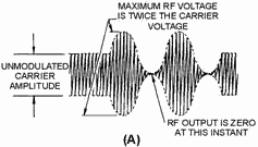
Figure 1-40A. - Conditions for 100-percent modulation. When analyzed, the modulation envelope consists of the unmodulated RF carrier voltage plus the combined
voltage of the two sidebands. The combined sideband voltages are approximately equal to the RF carrier voltage
since each sideband frequency contains one-half the carrier voltage, as shown in view (B). This condition is known
as 100-percent modulation and the maximum modulated RF voltage is twice the carrier voltage. The audio-modulating
voltage can be increased beyond the amount required to produce 100-percent modulation. When this happens, the
negative peak of the modulating signal becomes larger in amplitude than the dc plate-supply voltage to the final
power amplifier. This causes the final plate voltage to be negative for a short period of time near the negative
peak of the modulating signal. For the duration of the negative plate voltage, no RF energy is developed across
the plate tank circuit and the RF output voltage remains at 0, as shown in figure 1-41, view (A).
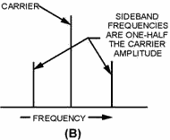
Figure 1-40B. - Conditions for 100-percent modulation. 1-46
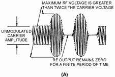
Figure 1-41A. - Overmodulation conditions. Look carefully at the modulation envelope in view (A). It shows that the negative peak of the modulating
signal has effectively been limited. If the signal were demodulated (detected in the receiver), it would have an
appearance somewhat similar to a square wave. This condition, known as OVERMODULATION, causes the signal to sound
severely distorted (although this will depend on the degree of overmodulation). Overmodulation will
generate unwanted (SPURIOUS) sideband frequencies. This effect can easily be detected by tuning a receiver near,
but somewhat outside the desired frequency. You would likely be able to tune to one or more of these undesired
sideband frequencies, but the reception would be severely distorted, possibly unintelligible. (Without
overmodulation, no such unwanted sideband frequencies would exist and you would be able to tune only to the
desired frequency.) These unwanted frequencies will appear for a considerable range both above and below the
desired channel. This effect is sometimes called SPLATTER. These spurious frequencies, shown in view (B), cause
interference with other stations operating on adjacent channels. You should clearly understand that
overmodulation, and its attendant distortion and interference is to be avoided.
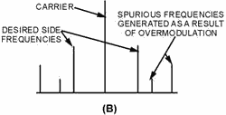
Figure 1-41B. - Overmodulation conditions. In addition to the above problems, overmodulation also causes abnormally large voltages and currents to
exist at various points within the transmitter. Therefore, sufficient overload protection by 1-47
circuit breakers and fuses should be provided. When this protection is not provided, the excessive
voltages can cause arcing between transformer windings and between the plates of capacitors, which will
permanently destroy the dielectric material. Excessive currents can also cause overheating of tubes and other
components. Ideally, you will want to operate a transmitter at 100-percent modulation so that you can
provide the maximum amount of energy in the sideband. However, because of the large and rapid fluctuations in
amplitude that these signals normally contain, this ideal condition is seldom possible. When the modulator is
properly adjusted, the loudest parts of the transmission will produce 100-percent modulation. The quieter parts of
the signal then produce lesser degrees of modulation.
To measure degrees of modulation less than 100 percent, you can use a MODULATION FACTOR (M) to indicate
the relative magnitudes of the RF carrier and the audio-modulating signal. Numerically, the modulation factor is: 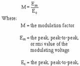
To illustrate this use of the equation, assume that a carrier wave with a peak amplitude of 400 volts is
modulated by a 3-kilohertz sine wave with a peak amplitude of 200 volts. The modulation factor is figured as
follows: 
If the modulation factor were multiplied by 100, the resultant quantity would be the PERCENT of MODULATION
(%M): 1-48

By using the correct equation, you can determine the percent of modulation from the modulation envelope
pattern. This method is useful when the percent of modulation is to be determined using the pattern on the screen
of an oscilloscope. For example, assume that your oscilloscope is connected to the output of a modulator circuit
and produces the screen pattern shown in figure 1-42. According to the setting of the calibration control, each
large division on the vertical scale is equal to 200 volts. By using this scale, you can see that the peak carrier
amplitude (unmodulated portion) is 400 volts. The peak amplitude of the carrier is designated as e0 in
figure 1-42. 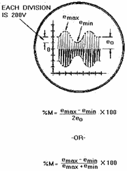
Figure 1-42. - Computing percent of modulation from the modulation envelope. The amplitude of the audio-modulating voltage can also be determined from amplitude variations in the
envelope pattern. Notice that the peak-to-peak variations in envelope amplitude (emax - e min)
is equal to 400 volts on the scale. Note then that the peak amplitude of the audio voltage is 200 volts. If these
RF and audio voltage values are inserted into the equation, the pattern in figure 1-42 is found to represent
50-percent modulation.
1-49
If Em and Ec in the equation are assumed to represent peak-to-peak values, the
following formula results: 
Since the peak-to-peak value of E m in figure 1-42 is emax - emin, we can substitute
as follows: 
Also, since the peak-to-peak value of the carrier Ec is 2 times e0, we can
substitute 2eo for Ec as follows: 
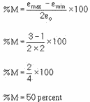
Linear vertical distance represents voltage on the screen of a cathode-ray tube. Vertical distance units
can be used in place of voltage in equations. Thus, if only the percent of modulation is required, the
oscilloscope need not be calibrated and the actual circuit voltages are not required. In figure 1-42, emax
represents 600 volts (3 large divisions); emin is 200 volts (1 division); and e0 is 400
volts (2 divisions). Using the equation and the dimensions of the screen pattern, you can figure the percent of
modulation as follows:
When e0 of the equation is difficult to measure, an alternative solution can be obtained with
the equation below:

VECTOR ANALYSIs of an AM WAVE. - You studied earlier in this chapter that the
modulation envelope results when the instantaneous sums of the carrier and sideband voltages are plotted with
respect to time. An attempt to add these three voltages, point-by-point, would prove to be a huge task. The same
end result can be obtained by using a rotating vector to represent each of the three
1-50
| - |
Matter, Energy,
and Direct Current |
| - |
Alternating Current and Transformers |
| - |
Circuit Protection, Control, and Measurement |
| - |
Electrical Conductors, Wiring Techniques,
and Schematic Reading |
| - |
Generators and Motors |
| - |
Electronic Emission, Tubes, and Power Supplies |
| - |
Solid-State Devices and Power Supplies |
| - |
Amplifiers |
| - |
Wave-Generation and Wave-Shaping Circuits |
| - |
Wave Propagation, Transmission Lines, and
Antennas |
| - |
Microwave Principles |
| - |
Modulation Principles |
| - |
Introduction to Number Systems and Logic Circuits |
| - |
- Introduction to Microelectronics |
| - |
Principles of Synchros, Servos, and Gyros |
| - |
Introduction to Test Equipment |
| - |
Radio-Frequency Communications Principles |
| - |
Radar Principles |
| - |
The Technician's Handbook, Master Glossary |
| - |
Test Methods and Practices |
| - |
Introduction to Digital Computers |
| - |
Magnetic Recording |
| - |
Introduction to Fiber Optics |
| Note: Navy Electricity and Electronics Training
Series (NEETS) content is U.S. Navy property in the public domain. |
|


