|
[Go to TOC] MIL-STD-1553 & 1773 DATA BUS
PURPOSE In recent years, the use of digital techniques in aircraft equipment has greatly increased,
as have the number of avionics subsystems and the volume of data processed by them. Because analog point-to-point wire bundles are inefficient
and cumbersome means of interconnecting the sensors, computers, actuators, indicators, and other equipment onboard the modern military vehicle,
a serial digital multiplex data bus was developed. MIL-STD-1553 defines all aspects of the bus, therefore, many groups working with the military
tri-services have chosen to adopt it. The 1553 multiplex data bus provides integrated, centralized system control and a standard interface
for all equipment connected to the bus. The bus concept provides a means by which all bus traffic is available to be accessed with a single
connection for testing and interfacing with the system. The standard defines operation of a serial data bus that interconnects multiple devices
via a twisted, shielded pair of wires. The system implements a command-response format. MIL-STD-1553, "Aircraft Internal Time-Division
Command/Response Multiplex Data Bus," has been in use since 1973 and is widely applied. MIL-STD-1553 is referred to as "1553" with the appropriate
revision letter (A or B) as a suffix. The basic difference between the 1553A and the 1553B is that in the 1553B, the options are defined rather
than being left for the user to define as required. It was found that when the standard did not define an item, there was no coordination in
its use. Hardware and software had to be redesigned for each new application. The primary goal of the 1553B was to provide flexibility without
creating new designs for each new user. This was accomplished by specifying the electrical interfaces explicitly so that compatibility between
designs by different manufacturers could be electrically interchangeable. The Department of Defense chose multiplexing because of the
following advantages:
- Weight reduction
- Simplicity
- Standardization
- Flexibility
Some 1553 applications utilize more than one data bus on a vehicle. This is often done, for example, to isolate a Stores bus from a Communications
bus or to construct a bus system capable of interconnecting more terminals than a single bus could accommodate. When multiple buses are used,
some terminals may connect to both buses, allowing for communication between them. MULTIPLEXING Multiplexing
facilitates the transmission of information along the data flow. It permits the transmission of several signal sources through one communications
system. BUS The bus is made up of twisted-shielded pairs of wires to maintain message integrity. MIL-STD-1553
specifies that all devices in the system will connect to a redundant pair of buses. This provides a second path for bus traffic should one of
the buses be damaged. Signals are only allowed to appear on one of the two buses at a time. If a message cannot be completed on one bus, the
bus controller may switch to the other bus. In some applications more than one 1553 bus may be implemented on a given vehicle. Some terminals
on the bus may actually connect to both buses. BUS COMPONENTS There are only three functional
modes of terminals allowed on the data bus: the bus controller, the bus monitor, and the remote terminal. Devices may be capable of more than
one function. Figure 1 illustrates a typical bus configuration.
 Figure 1. 1553 Bus Structure
- Bus Controller - The bus controller (BC) is the terminal that initiates information transfers on the data bus. It sends commands to
the remote terminals which reply with a response. The bus will support multiple controllers, but only one may be active at a time. Other requirements,
according to 1553, are: (1) it is "the key part of the data bus system," and (2) "the sole control of information transmission on the bus shall
reside with the bus controller."
- Bus Monitor - 1553 defines the bus monitor as "the terminal assigned the task of receiving bus traffic and extracting selected information
to be used at a later time." Bus monitors are frequently used for instrumentation.
- Remote Terminal - Any terminal not operating in either the bus controller or bus monitor mode is
operating in the remote terminal
(RT) mode. Remote terminals are the largest group of bus components. MODULATION The signal is
transferred over the data bus using serial digital pulse code modulation. DATA ENCODING The
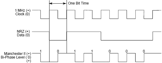
type of data encoding used by 1553 is Manchester II biphase. - A logic one (1) is transmitted as a bipolar coded signal 1/0 (in other
words, a positive pulse followed by a negative pulse).
- A logic zero (0) is a bipolar coded signal 0/1 (i.e., a negative pulse followed by a positive pulse).

Figure
2. Data Encoding
A transition through zero occurs at the midpoint of each bit, whether the rate is a logic one or a logic zero. Figure 2 compares a commonly
used Non Return to Zero (NRZ) code with the Manchester II biphase level code, in conjunction with a 1 MHz clock.
BIT TRANSMISSION RATE The bit transmission rate on the bus is 1.0 megabit per second with a combined accuracy
and long-term stability of +/- 0.1%. The short-term stability is less than 0.01%. There are 20 1.0-microsecond bit times allocated
for each word. All words include a 3 bit-time sync pattern, a 16-bit data field that is specified differently for each word type, and 1 parity
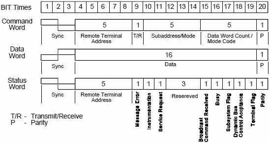
check bit. WORD FORMATS Bus traffic or communications travels along the bus in words. A word in MIL-STD-1553
is a sequence of 20 bit times consisting of a 3 bit-time sync wave form, 16 bits of data, and 1 parity check bit. This is the word as it is
transmitted on the bus; 1553 terminals add the sync and parity before transmission and remove them during reception. Therefore, the nominal
word size is 16 bits, with the most significant bit (MSB) first. There are three types of words: command, status, and data. A packet is defined
to have no intermessage gaps. The time between the last word of a controller message and the return of the terminal status byte is 4-12 microseconds.
The time between status byte and the next controller message is undefined. Figure 3 illustrates these three formats.

Figure
3. 1553 Word Formats
COMMAND WORD Command words are transmitted only by the bus controller and always consist of:
- 3 bit-time sync pattern
- 5 bit RT address field
- 1 Transmit/Receive (T/R) field
- 5 bit subaddress/mode field
- 5 bit word count/mode code field
- 1 parity check bit.
DATA WORD Data words are transmitted either by the BC or by the RT
in response to a BC request. The standard allows a maximum of 32 data words to be sent in a packet with a command word before a status response
must be returned. Data words always consist of:
- 3 bit-time sync pattern (opposite in polarity from command and status words)
- 16 bit data field
- 1 parity check bit.
STATUS WORD Status words are transmitted by the RT in response to command
messages from the BC and consist of:
- 3 bit-time sync pattern (same as for a command word)
- 5 bit address of the responding RT
- 11 bit status field
- 1 parity check bit.
The 11 bits in the status field are used to notify the BC of the operating condition of the RT and subsystem.
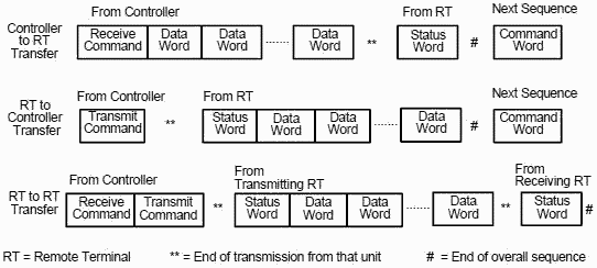
INFORMATION TRANSFERS Three basic types of information transfers are defined by 1553:
- Bus Controller to Remote Terminal transfers
- Remote Terminal to Bus Controller transfers
- Remote Terminal to Remote Terminal transfers
These transfers are related to the data flow and are referred to as messages. The basic formats of these messages are shown in Figure 4.

Figure 4. 1553 Data Message Formats
The normal command/response operation involves the transmission of a command from the BC to a selected RT address. The RT either accepts
or transmits data depending on the type (receive/transmit) of command issued by the BC. A status word is transmitted by the RT in response to
the BC command if the transmission is received without error and is not illegal. Figure 5 illustrates the 1553B Bus Architecture in a
typical aircraft. 
Figure 5. Typical Bus Architecture
MIL-STD-1773 MIL-STD-1773 contains the requirements for utilizing a fiber optic "cabling" system
as a transmission medium for the MIL-STD-1553B bus protocol. As such, the standard repeats MIL-STD-1553 nearly word-for-word. The standard
does not specify power levels, noise levels, spectral characteristics, optical wavelength, electrical/optical isolation or means of distributing
optical power. These must be contained in separate specifications for each intended use. Data encoding and word format are identical
to MIL-STD-1553, with the exception that pulses are defined as transitions between 0 (off) and 1 (on) rather than between + and - voltage transitions
since light cannot have a negative value. Since the standard applies to cabling only, the bus operates at the same speed as it would
utilizing wire. Additionally, data error rate requirements are unchanged. Different environmental considerations must be given to fiber
optic systems. Altitude, humidity, temperature, and age affects fiber optics differently than wire conductors. Power is divided evenly at junctions
which branch and connectors have losses just as wire connectors do.
Table of Contents for Electronics Warfare and Radar Engineering Handbook
Introduction |
Abbreviations | Decibel | Duty
Cycle | Doppler Shift | Radar Horizon / Line
of Sight | Propagation Time / Resolution | Modulation
| Transforms / Wavelets | Antenna Introduction
/ Basics | Polarization | Radiation Patterns |
Frequency / Phase Effects of Antennas |
Antenna Near Field | Radiation Hazards |
Power Density | One-Way Radar Equation / RF Propagation
| Two-Way Radar Equation (Monostatic) |
Alternate Two-Way Radar Equation |
Two-Way Radar Equation (Bistatic) |
Jamming to Signal (J/S) Ratio - Constant Power [Saturated] Jamming
| Support Jamming | Radar Cross Section (RCS) |
Emission Control (EMCON) | RF Atmospheric
Absorption / Ducting | Receiver Sensitivity / Noise |
Receiver Types and Characteristics |
General Radar Display Types |
IFF - Identification - Friend or Foe | Receiver
Tests | Signal Sorting Methods and Direction Finding |
Voltage Standing Wave Ratio (VSWR) / Reflection Coefficient / Return
Loss / Mismatch Loss | Microwave Coaxial Connectors |
Power Dividers/Combiner and Directional Couplers |
Attenuators / Filters / DC Blocks |
Terminations / Dummy Loads | Circulators
and Diplexers | Mixers and Frequency Discriminators |
Detectors | Microwave Measurements |
Microwave Waveguides and Coaxial Cable |
Electro-Optics | Laser Safety |
Mach Number and Airspeed vs. Altitude Mach Number |
EMP/ Aircraft Dimensions | Data Busses | RS-232 Interface
| RS-422 Balanced Voltage Interface | RS-485 Interface |
IEEE-488 Interface Bus (HP-IB/GP-IB) | MIL-STD-1553 &
1773 Data Bus | This HTML version may be printed but not reproduced on websites.
|


