|
[Go to TOC]
SUPPORT JAMMING
The following table contains a summary of equations developed in this section: 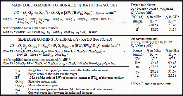
 Support
jamming adds a few geometric complexities. A SOJ platform usually uses high gain, directional antennas. Therefore, the jamming antenna must
not only be pointed at the victim radar, but there must be alignment of radar, targets, and SOJ platform for the jamming to be effective. Two
cases will be described, main lobe-jamming and side-lobe jamming. Support
jamming adds a few geometric complexities. A SOJ platform usually uses high gain, directional antennas. Therefore, the jamming antenna must
not only be pointed at the victim radar, but there must be alignment of radar, targets, and SOJ platform for the jamming to be effective. Two
cases will be described, main lobe-jamming and side-lobe jamming.
Support jamming is usually applied against search and acquisition
radars which continuously scan horizontally through a volume of space. The scan could cover a sector or a full 360°. The horizontal antenna
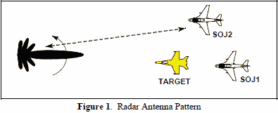
pattern of the radar will exhibit a main lobe and side lobes as illustrated in Figure 1. The target is detected when the main lobe sweeps across
it. For main lobe jamming, the SOJ platform and the target(s) must be aligned with the radar's main lobe as it sweeps the target(s).
For side lobe jamming, the SOJ platform may be aligned with one or more of the radar's side lobes when the main lobe sweeps the target. The
gain of a radar's side lobes are many tens of dB less (usually more than 30 dB less) than the gain of the main lobe, so calculations of side
lobe jamming must use the gain of the side lobe for the radar receive antenna gain, not the gain of the main lobe. Also, because many modern
radars employ some form of side lobe blanking or side lobe cancellation, some knowledge of the victim radar is required for the employment of
side lobe jamming. 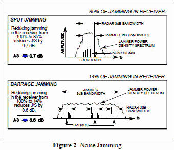 All radar receivers are frequency selective. That is, they are filters that allow only a narrow range of
frequencies into the receiver circuitry. DECM, by definition, creates forgeries of the real signal and, ideally, are as well matched to the
radar receiver as the real signal. On the other hand, noise jamming probably will not match the radar receiver bandwidth characteristics. Noise
jamming is either spot jamming or barrage jamming. As illustrated in Figure 2, spot jamming is simply narrowing the bandwidth of the noise jammer
so that as much of the jammer power as possible is in the radar receiver bandwidth. Barrage jamming is using a wide noise bandwidth to cover
several radars with one jammer or to compensate for any uncertainty in the radar frequency. In both cases some of the noise power is "wasted"
because it is not in the radar receiver filter. All radar receivers are frequency selective. That is, they are filters that allow only a narrow range of
frequencies into the receiver circuitry. DECM, by definition, creates forgeries of the real signal and, ideally, are as well matched to the
radar receiver as the real signal. On the other hand, noise jamming probably will not match the radar receiver bandwidth characteristics. Noise
jamming is either spot jamming or barrage jamming. As illustrated in Figure 2, spot jamming is simply narrowing the bandwidth of the noise jammer
so that as much of the jammer power as possible is in the radar receiver bandwidth. Barrage jamming is using a wide noise bandwidth to cover
several radars with one jammer or to compensate for any uncertainty in the radar frequency. In both cases some of the noise power is "wasted"
because it is not in the radar receiver filter.
In the past, noise jammers were often described as having so many "watts per
MHz". This is nothing more than the power of the noise jammer divided by the noise bandwidth. That is, a 500 watt noise jammer transmitting
a noise bandwidth of 200 MHz has 2.5 watts/MHz. Older noise jammers often had noise bandwidths that were difficult, or impossible, to adjust
accurately. These noise jammers usually used manual tuning to set the center frequency of the noise to the radar frequency. Modern noise jammers
can set on the radar frequency quite accurately and the noise bandwidth is selectable, so the noise bandwidth is more a matter of choice than
it used to be, and it is possible that all of the noise is placed in the victim radar's receiver. If, in the example above, the 500 watt
noise jammer were used against a radar that had a 3 MHz receiver bandwidth, the noise jammer power applicable to that radar would be: 3 MHz x 2.5 watts/MHz = 7.5 watts → 38.75 dBm
[1]
The calculation must be done as shown in equation [1] - multiply the watts/MHz by the radar bandwidth first and then convert to dBm.
You can't convert to dBm/MHz and then multiply. (See derivation of dB in Section 2-4) An alternate method for dB calculations is to use
the bandwidth reduction factor (BF). The BF is:  [2]
[2]
where: BWJ is the bandwidth of the noise jammer, and BWR is the bandwidth of the radar receiver. The power of the
jammer in the jamming equation (PJ) can be obtained by either method. If equation [1] is used then PJ is simply 38.75
dBm. If equation [2] is used then the jamming equation is written using (PJ - BF). All the following discussion uses the second method.
Which ever method is used, it is required that BWJ ≥ BWR. If BWJ < BWR, then all the available power is
in the radar receiver and equation [1] does not apply and the BF = 0. 
MAIN LOBE STAND-OFF / STAND-IN JAMMING The equivalent circuit shown in Figure 3 applies to main lobe jamming by a stand-off
support aircraft or a stand-in RPV. Since the jammer is not on the target aircraft, only two of the three ranges and two of the three space
loss factors (α's) are the same. Figure 3 differs from the J/S monostatic equivalent circuit shown in Figure 4 in
Section 4-7 in that the space loss from the jammer to the radar receiver is different.
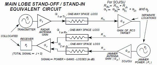
Figure 3. Main Lobe Stand-Off / Stand-In ECM Equivalent Circuit The equations are the same for both SOJ and SIJ. From the one way range equation in Section 4-3, and with inclusion of BF losses:

[3]
From the two way range equation in Section 4.4:  [4]
[4] so  [5] [5]
Note: Keep R and F in the same units. Converting to dB and using 10 log 4π = 10.99 dB:
10 log J/S = 10 log Pj - 10 log [BWj/BWR] + 10 log Gja - 10 log Pt - 10 log Gt - 10 log σ... [6]
+ 10.99 dB + 40 log RTx - 20 log RJx
If the simplified radar equation is used, the free space loss from the SOJ/SIJ to the radar receiver is αJx,
then equation [7] is the same as monostatic equation [6] in Section 4-7 except αJx replaces
α, and the bandwidth reduction factor [BF] losses are included: 10 log J = 10 log
Pj - BF + 10 log Gja + 10 log Gr - αJx (factors in dB)
[7] Since the free space loss from the radar to the target and return is the same both ways, αTx
= αRx = α1, equation [8] is the same as monostatic equation [7]
in Section 4-7.
10 log S = 10 log Pt + 10 log Gt + 10 log Gr + Gσ - 2α1 (factors in dB) [8]
and 10 log J/S = 10 log Pj - BF + 10 log Gja - αJx
- 10 log Pt - 10 log Gt - Gσ + 2α1 (factors in dB) [9]
Notice that unlike equation [8] in Section 4-7, there are two different α's in [9] because the signal paths are
different. SIDE LOBE STAND-OFF / STAND-IN JAMMING The equivalent circuit shown in Figure 4. It differs from Figure 3, (main lobe
SOJ/SIJ) in that the radar receiver antenna gain is different for the radar signal return and the jamming.
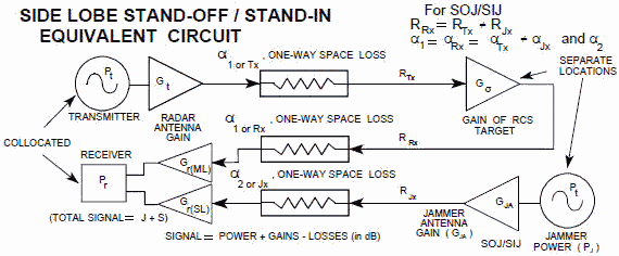
Figure 4. Side Lobe Stand-Off / Stand-In ECM Equivalent Circuit To calculate side lobe jamming, the gain of the radar antenna's side lobes must be known or estimated. The gain of each side lobe will
be different than the gain of the other side lobes. If the antenna is symmetrical, the first side lobe is the one on either side of the main
lobe, the second side lobe is the next one on either side of the first side lobe, and so on. The side lobe gain is GSLn , where the
'n' subscript denotes side lobe number: 1, 2, ..., n. The signal is the same as main lobe equations [4] and [8], except
Gr = Gr(ML)
 [10]
[10]
If simplified radar equations are used:
10 log S = 10 log Pt + 10 log Gt + 10 log Gr(ML) + Gσ - 2α1 (factors in dB)
The jamming equation is the same as main lobe equations [3] and [7] except
Gr = Gr(SL):  [11] [11]
10 log J = 10 log Pj - BF + 10 log Gja + 10 log Gr(SL) -
αJx (factors in dB) [12]
so  [13] [13]
Note: keep R and F in same units. Converting to dB and using 10 log 4B = 10.99 dB: 10 log J/S = 10 log Pj
- BF + 10 log Gja + 10 log Gr(SL) - 10 log Pt - 10 log Gt - 10 log Gr(ML) ...
[14]
- 10 log σ + 10.99 dB + 40 log RTx - 20 log RJx
(factors in dB)
If simplified radar equations are used: 10 log J/S = 10 log Pj - BF + 10
log Gja + 10 log Gr(SL) - αJx - 10 log Pt - 10 log Gt ...
[15]
- 10 log Gr(ML) - Gσ + 2α1 (in dB)
Table of Contents for Electronics Warfare and Radar Engineering Handbook
Introduction |
Abbreviations | Decibel | Duty
Cycle | Doppler Shift | Radar Horizon / Line
of Sight | Propagation Time / Resolution | Modulation
| Transforms / Wavelets | Antenna Introduction
/ Basics | Polarization | Radiation Patterns |
Frequency / Phase Effects of Antennas |
Antenna Near Field | Radiation Hazards |
Power Density | One-Way Radar Equation / RF Propagation
| Two-Way Radar Equation (Monostatic) |
Alternate Two-Way Radar Equation |
Two-Way Radar Equation (Bistatic) |
Jamming to Signal (J/S) Ratio - Constant Power [Saturated] Jamming
| Support Jamming | Radar Cross Section (RCS) |
Emission Control (EMCON) | RF Atmospheric
Absorption / Ducting | Receiver Sensitivity / Noise |
Receiver Types and Characteristics |
General Radar Display Types |
IFF - Identification - Friend or Foe | Receiver
Tests | Signal Sorting Methods and Direction Finding |
Voltage Standing Wave Ratio (VSWR) / Reflection Coefficient / Return
Loss / Mismatch Loss | Microwave Coaxial Connectors |
Power Dividers/Combiner and Directional Couplers |
Attenuators / Filters / DC Blocks |
Terminations / Dummy Loads | Circulators
and Diplexers | Mixers and Frequency Discriminators |
Detectors | Microwave Measurements |
Microwave Waveguides and Coaxial Cable |
Electro-Optics | Laser Safety |
Mach Number and Airspeed vs. Altitude Mach Number |
EMP/ Aircraft Dimensions | Data Busses | RS-232 Interface
| RS-422 Balanced Voltage Interface | RS-485 Interface |
IEEE-488 Interface Bus (HP-IB/GP-IB) | MIL-STD-1553 &
1773 Data Bus | This HTML version may be printed but not reproduced on websites.
|


 Support
jamming adds a few geometric complexities. A SOJ platform usually uses high gain, directional antennas. Therefore, the jamming antenna must
not only be pointed at the victim radar, but there must be alignment of radar, targets, and SOJ platform for the jamming to be effective. Two
cases will be described, main lobe-jamming and side-lobe jamming.
 All radar receivers are frequency selective. That is, they are filters that allow only a narrow range of
frequencies into the receiver circuitry. DECM, by definition, creates forgeries of the real signal and, ideally, are as well matched to the
radar receiver as the real signal. On the other hand, noise jamming probably will not match the radar receiver bandwidth characteristics. Noise
jamming is either spot jamming or barrage jamming. As illustrated in Figure 2, spot jamming is simply narrowing the bandwidth of the noise jammer
so that as much of the jammer power as possible is in the radar receiver bandwidth. Barrage jamming is using a wide noise bandwidth to cover
several radars with one jammer or to compensate for any uncertainty in the radar frequency. In both cases some of the noise power is "wasted"
because it is not in the radar receiver filter.
 [2]
[2]


 [4]
[4] [5]
[5]
 [10]
[10] [11]
[11] [13]
[13]