Module 3 -- Introduction to Circuit Protection, Control, and Measurement
Pages i,
1-1,
1-11,
1-21,
1-31,
1-41,
1-51,
1-61,
1-71,
2-1,
2-11,
1-21,
2-31,
2-41,
3-1,
3-11,
3-21,
3-31,
AI-1,
AII-1,
AIII-1,
IV-1,
Index
Chapter 1 - Circuit Measurement
Learning Objectives
Learning objectives are stated at the beginning of each chapter. These learning
objectives serve as a preview of the information you are expected to learn in the
chapter. The comprehensive check questions are based on the objectives. By successfully
completing the NRTC, you indicate that you have met the objectives and have learned
the information. The learning objectives are listed below.
Upon completion of this chapter you will be able to:
1. State two ways circuit measurement is used, why in-circuit meters
are used, and one advantage of out-of-circuit meters.
2. State the way in which a compass reacts to a conducting wire including
the compass reaction to increasing and decreasing dc and ac high and low frequencies.
3. State how a d'Arsonval meter movement reacts to dc.
4. State the purpose of a rectifier as used in ac meters.
5. State the meaning of the term "damping" as it applies to meter
movements and describe two methods by which damping is accomplished.
6. Identify average value as the value of ac measured and effective
value (rms) as the ac value indicated on ac meter scales.
7. Identify three meter movements that measure dc or ac without the use of a rectifier.
8. State the electrical quantity measured by an ammeter, the way
in which an ammeter is connected in a circuit, and the effect of an ammeter upon
a circuit.
9. Define ammeter sensitivity.
10. State the method used to allow an ammeter to measure different
ranges and the reason for using the highest range when connecting an ammeter to
a circuit.
11. List the safety precautions for ammeter use.
12. State the electrical quantity measured by a voltmeter, the way
in which a voltmeter is connected
in a circuit, the way in which a voltmeter affects the circuit being measured,
and the way in which a voltmeter is made from a current reacting meter movement.
13. Define voltmeter sensitivity.
14. State the method used to allow a voltmeter to measure different
ranges and the reason for using the highest range when connecting a voltmeter to
a circuit.
15. Identify the type of meter movement that reacts to voltage and
the most common use of this movement.
16. List the safety precautions for voltmeter use.
17. State the electrical quantity measured by an ohmmeter, the second use of an ohmmeter, and the way in which an ohmmeter is connected to a resistance
being measured.
18. State the method used to allow an ohmmeter to measure different
ranges and the area of an ohmmeter scale that should be used when measuring resistance.
19. State the two types of ohmmeters and the way in which each can
be identified.
20. List the safety precautions for ohmmeter use.
21. State the primary reason for using a megger and the method of
using it.
22. Identify normal and abnormal indications on a megger.
23. List the safety precautions for megger use.
24. State how a multimeter differs from other meters, the reason
a multimeter is preferred over separate meters, and the way in which a multimeter
is changed from a voltage measuring device to a current measuring device.
25. State the reason the ac and dc scales of a multimeter differ,
the reason for having a mirror on the scale of a multimeter, and the proper way
of reading a multimeter using the mirror.
26. List the safety precautions for multimeter use.
27. State the purpose of a hook-on type voltmeter.
28. State the electrical quantity measured by a wattmeter and a watt-hour
meter.
29. Identify the two types of frequency meters.
30. Identify the type of meter and interpret the meter reading from
scale presentations of an ammeter; a voltmeter; an ohmmeter; a megger; a multimeter
(current, voltage, and resistance examples); a wattmeter; a watt-hour meter; and
a frequency meter (vibrating reed and moving-disk types).
Circuit Measurement
This chapter will acquaint you with the basics of circuit measurement and some
of the devices used to measure voltage, current, resistance, power, and frequency.
There are other quantities involved in electrical circuits, such as capacitance,
inductance, impedance, true power, and effective power. It is possible to measure
any circuit quantity once you are able to select and use the proper circuit measuring
device. You will NOT know all there is to know about circuit measuring devices (test
equipment) when you finish this chapter. That is beyond the scope of this chapter
and even beyond the scope of this training series. However, more information on
test equipment is provided in another portion of this training series.
A question which you might ask before starting this chapter is "Why do I need
to know about circuit measurement?"
If you intend to accomplish anything in the field of electricity and electronics,
you must be aware of the forces acting inside the circuits with which you work.
Modules 1 and 2 of this training series introduced you to the physics involved in
the study of electricity and to the fundamental concepts of direct and alternating
current. The terms voltage (volts), current (amperes), and resistance (ohms) were
explained, as well as the various circuit elements; e.g., resistors, capacitors,
inductors, transformers, and batteries.
In explaining these terms and elements to you, schematic symbols and schematic
diagrams were used. In many of these schematic diagrams, a meter was represented
in the circuit, as shown in figure 1-1.
Figure 1-1 - a simple representative circuit.
As you recall, the current in a dc circuit with 6 volts across a 6-ohm resistor
is 1 ampere. The "A" in figure 1-1 is the symbol for an ammeter. An ammeter is a
device that measures current. The name "ammeter" comes from the fact that it is
a meter used to measure current (in amperes), and thus is called an Ampere Meter,
or AMMETER. The ammeter in figure 1-1 is measuring a current of 1 ampere with the
voltage and resistance values given.
In the discussion and explanation of electrical and electronic circuits, the
quantities in the circuit (voltage, current, and resistance) are important. If you
can measure the electrical quantities in a circuit, it is easier to understand what
is happening in that circuit. This is especially true when you are troubleshooting
defective circuits. By measuring the voltage, current, capacitance, inductance,
impedance, and resistance in a circuit, you can determine why the circuit is not
doing what it is supposed to do. For instance, you can determine why a radio is
not receiving or transmitting, why your automobile will not start, or why an electric
oven is not working. Measurement will also assist you in determining why an electrical
component (resistor, capacitor, inductor) is not doing its job.
The measurement of the electrical parameters quantities in a circuit is an essential
part of working on electrical and electronic equipment.
Introduction to Circuit Measurements
Circuit measurement is used to monitor the operation of an electrical or electronic
device, or to determine the reason a device is not operating properly. Since electricity
is invisible, you must use some sort of device to determine what is happening in
an electrical circuit. Various devices called test equipment are used to measure
electrical quantities. The most common types of test equipment use some kind of
metering device.
In-Circuit Meters
Some electrical and electronic devices have meters built into them. These meters
are known as in- circuit meters. An in-circuit meter is used to monitor
the operation of the device in which it is installed. Some examples of in-circuit
meters are the generator or alternator meter on some automobiles; the voltage, current,
and frequency meters on control panels at electrical power plants; and the electrical
power meter that records the amount of electricity used in a building.
It is not practical to install an in-circuit meter in every circuit. However,
it is possible to install an in- circuit meter in each critical or representative
circuit to monitor the operation of a piece of electrical equipment. a mere glance
at or scan of the in-circuit meters on a control board is often sufficient to tell
if the equipment is working properly.
While an in-circuit meter will indicate that an electrical device is not functioning
properly, the cause of the malfunction is determined by troubleshooting. Troubleshooting
is the process of locating and repairing faults in equipment after they
have occurred. Since troubleshooting is covered elsewhere in this training series,
it will be mentioned here only as it applies to circuit measurement.
Out-of-Circuit Meters
In troubleshooting, it is usually necessary to use a meter that can be connected
to the electrical or electronic equipment at various testing points and may be moved
from one piece of equipment to another. These meters are generally portable and
self-contained, and are known as out-of-circuit meters.
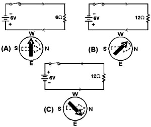
Figure 1-2 - Compass and conductor with direct current.
Out-of-circuit meters are more versatile than in-circuit meters in that the out-of-circuit
meter can be used wherever you wish to connect it. Therefore, the out-of-circuit
meter is more valuable in locating the cause of a malfunction in a device.
Q1. What are two ways that circuit measurement is used?
Q2. Why are in-circuit meters used?
Q3. What is one advantage of an out-of-circuit meter when it
is compared with an in-circuit meter?
Basic Meter Movements
The meter movement is, as the name implies, the part of a meter that moves. a
meter movement converts electrical energy into mechanical energy. There are many
different types of meter movements. The first one you will learn about is based
upon a principle with which you are already familiar. That principle is the interaction
of magnetic fields.
Compass and Conducting Wire
You know that an electrical conductor in which current flows has a magnetic field
generated around it. If a compass is placed close to the conductor, the compass
will react to that magnetic field (fig. 1-2).
If the battery is disconnected, the north end of the compass needle will point
to magnetic north, as illustrated in figure 1-2(A) by the broken-line compass needle
pointing to the right. When the battery is connected, current flows through the
circuit and the compass needle aligns itself with the magnetic field of the conductor,
as indicated by the solid compass needle. The strength of the magnetic field created
around the conductor is dependent upon the amount of current.
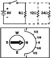
Figure 1-3 - a simple meter from a compass.
Figure 1-4 - a movable coil in a magnetic field (no current).
Figure 1-5. - a movable coil in a magnetic field (current).
In figure 1-2(A), the resistance in the circuit is 6 ohms. With the 6-volt battery
shown, current in the circuit is 1 ampere. In figure 1-2(B), the resistance has
been changed to 12 ohms. With the 6-volt battery shown, current in the circuit is
1/2 or .5 ampere. The magnetic field around the conductor in figure 1-2(B) is weaker
than the magnetic field around the conductor in figure 1-2(A). The compass needle
in figure 1-2(B) does not move as far from magnetic north.
If the direction of the current is reversed, the compass needle will move in
the opposite direction because the polarity of the magnetic field has reversed.
In figure 1-2(C), the battery connections are reversed and the compass needle
now moves in the opposite direction.
You can construct a crude meter to measure current by using a compass and a piece
of paper. By using resistors of known values, and marking the paper to indicate
a numerical value, as in figure 1-3, you have a device that measures current.
This is, in fact, the way the first GALVANOMETERS were developed. a galvanometer
is an instrument that measures small amounts of current and is based on the electromagnetic
principle. a galvanometer can also use the principles of electrodynamics, which
will be covered later in this topic.
The meter in figure 1-3 is not very practical for electrical measurement. The
amount the compass needle swings depends upon the closeness of the compass to the
conductor carrying the current, the direction of the conductor in relation to magnetic
north, and the influence of other magnetic fields. In addition, very small amounts
of current will not overcome the magnetic field of the Earth and the needle will
not move.
Q4. How does a compass react when placed close to a current carrying
conductor?
Q5. If the amount of current in the conductor changes, what happens
to the magnetic field around the conductor?
Q6. How does the compass needle react to a decreased magnetic
field?
Permanent-Magnet Moving-Coil Movement
The compass and conducting wire meter can be considered a fixed-conductor moving-magnet
device since the compass is, in reality, a magnet that is allowed to move. The basic
principle of this device is the interaction of magnetic fields-the field of the
compass (a permanent magnet) and the field around the conductor (a simple electromagnet).
A permanent-magnet moving-coil movement is based upon a fixed permanent magnet
and a coil of wire which is able to move, as in figure 1-4. When the switch is closed,
causing current through the coil, the coil will have a magnetic field which will
react to the magnetic field of the permanent magnet. The bottom portion of the coil
in figure 1-4 will be the north pole of this electromagnet. Since opposite poles
attract, the coil will move to the position shown in figure 1-5.
Figure 1-6 - a basic coil arrangement.
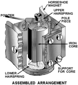
Figure 1-9 - Assembled meter movement.
The coil of wire is wound on an aluminum frame, or bobbin, and the bobbin is
supported by jeweled bearings which allow it to move freely. This is shown in figure
1-6.
To use this permanent-magnet moving-coil device as a meter, two problems must
be solved. First, a way must be found to return the coil to its original position
when there is no current through the coil. Second, a method is needed to indicate
the amount of coil movement.
The first problem is solved by the use of hairsprings attached to each end of
the coil as shown in figure 1-7. These hairsprings can also be used to make the
electrical connections to the coil. With the use of hairsprings, the coil will return
to its initial position when there is no current. The springs will also tend to
resist the movement of the coil when there is current through the coil. When the
attraction between the magnetic fields (from the permanent magnet and the coil)
is exactly equal to the force of the hairsprings, the coil will stop moving toward
the magnet.
Figure 1-7 - Coil and hairsprings.
Figure 1-8 - a complete coil.
As the current through the coil increases, the magnetic field generated around
the coil increases. The stronger the magnetic field around the coil, the farther
the coil will move. This is a good basis for a meter.
But, how will you know how far the coil moves? If a pointer is attached to the
coil and extended out to a scale, the pointer will move as the coil moves, and the
scale can be marked to indicate the amount of current through the coil. This is
shown in figure 1-8.
Two other features are used to increase the accuracy and efficiency of this meter
movement. First, an iron core is placed inside the coil to concentrate
the magnetic fields. Second, curved pole pieces are
attached to the magnet to ensure that the turning force on the coil increases
steadily as the current increases.
The meter movement as it appears when fully assembled is shown in figure 1-9.
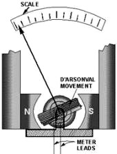
Figure 1-10 - a meter using d'Arsonval movement.
This permanent-magnet moving-coil meter movement is the basic movement in most
measuring instruments. It is commonly called the d'Arsonval movement because it
was first employed by the Frenchman d'Arsonval in making electrical measurements.
Figure 1-10 is a view of the d'Arsonval meter movement used in a meter.
Q7. What type of meter movement is the d'Arsonval meter movement?
Q8. What is the effect of current flow through the coil in a
d'Arsonval meter movement? Q9. What are three functions of the hairsprings
in a d'Arsonval meter movement?
Compass and Alternating Current
Up to this point, only direct current examples have been used. What happens with
the use of alternating current? Figure 1-11 shows a magnet close to a conductor
carrying alternating current at a frequency of 1 hertz.
The compass needle will swing toward the east part of the compass (down) as the
current goes positive, as represented in figure 1-11(A). (The sine wave of the current
is shown in the lower portion of the figure to help you visualize the current in
the conductor.)
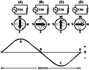
Figure 1-11 - Compass and conductor with ac.
In figure 1-11(B), the current returns to zero, and the compass needle returns
to magnetic north (right). As the current goes negative, as in figure 1-11(C), the
compass needle swings toward the west portion of the compass (up). The compass needle
returns to magnetic north as the current returns to zero as shown in figure 1-11(D).
This cycle of the current going positive and negative and the compass swinging
back and forth will continue as long as there is alternating current in the conductor.
If the frequency of the alternating current is increased, the compass needle
will swing back and forth at a higher rate (faster). At a high enough frequency,
the compass needle will not swing back and forth, but simply vibrate around the
magnetic north position. This happens because the needle cannot react fast enough
to the very rapid current alternations. The compass (a simple meter) will indicate
the average value of the alternating current (remember the average value of a sine
wave is zero) by vibrating around the zero point on the meter (magnetic north).
This is not of much use if you wish to know the value of the alternating current.
Some device, such as a rectifier, is needed to allow the compass to react to the
alternating current in a way that can be useful in measuring the current.
Posted July 22, 2021
|


