Module 8 - Introduction to Amplifiers
Pages i,
1-1,
1-11,
1-21,
1-31,
2-1,
2-11,
2-21,
2-31,
3-1,
3-11,
3-21,
3-31,
3-41,
3-51,
3-61,
AI-1,
Index
| - |
Matter, Energy,
and Direct Current |
| - |
Alternating Current and Transformers |
| - |
Circuit Protection, Control, and Measurement |
| - |
Electrical Conductors, Wiring Techniques,
and Schematic Reading |
| - |
Generators and Motors |
| - |
Electronic Emission, Tubes, and Power Supplies |
| - |
Solid-State Devices and Power Supplies |
| - |
Amplifiers |
| - |
Wave-Generation and Wave-Shaping Circuits |
| - |
Wave Propagation, Transmission Lines, and
Antennas |
| - |
Microwave Principles |
| - |
Modulation Principles |
| - |
Introduction to Number Systems and Logic Circuits |
| - |
- Introduction to Microelectronics |
| - |
Principles of Synchros, Servos, and Gyros |
| - |
Introduction to Test Equipment |
| - |
Radio-Frequency Communications Principles |
| - |
Radar Principles |
| - |
The Technician's Handbook, Master Glossary |
| - |
Test Methods and Practices |
| - |
Introduction to Digital Computers |
| - |
Magnetic Recording |
| - |
Introduction to Fiber Optics |
| Note: Navy Electricity and Electronics Training
Series (NEETS) content is U.S. Navy property in the public domain. |
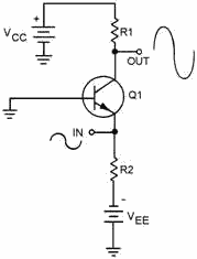
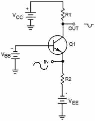
The Class of Operation of a transistor amplifier is determined
by the percent of time that current flows through the transistor in relation to
the input signal.
In Class a Operation, transistor current flows for 100% (360º)
of the input signal. Class a operation is the least efficient class of operation,
but provides the best fidelity.
In Class AB Operation, transistor current flows for more than
50% but less than 100% of the input signal.
1-31
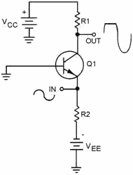
In Class B Operation, transistor current flows for 50% of the
input signal.
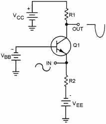
In Class C Operation, transistor current flows for less than
50% of the input signal. Class C operation is the most efficient class of operation.
1-32
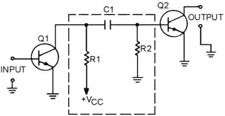
Coupling is used to transfer a signal from one stage to another.
Direct Coupling is the connection of the output of one stage
directly to the input of the next stage. This method is not used very often due
to the complex power supply requirements and impedance- matching problems.
RC Coupling is the most common method of coupling and uses a
coupling capacitor and signal-developing resistors.
1-33
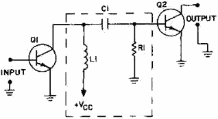
Impedance Coupling uses a coil as a load for the first stage
but otherwise functions just as RC coupling. Impedance coupling is used at high
frequencies.
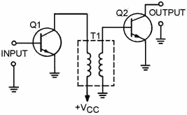
Transformer Coupling uses a transformer to couple the signal
from one stage to the next. Transformer coupling is very efficient and the transformer
can aid in impedance matching.
1-34
Maximum Power Transfer occurs between two circuits when the
output impedance of the first circuit matches the input impedance of the second
circuit.
A Maximum Voltage Input Signal is present when the input impedance
of the second circuit is larger than the output impedance of the first circuit (mismatched).
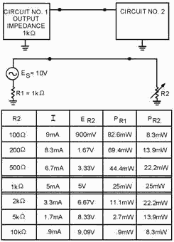
1-35
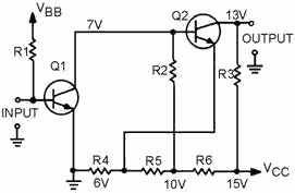
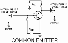
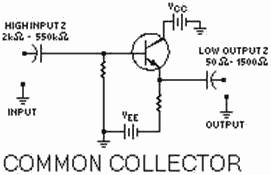
The Common-Emitter configuration of a transistor amplifier has
MEDIUM Input and MEDIUM Output Impedance.
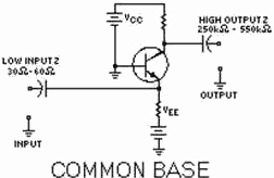
The Common-Base configuration of a transistor amplifier has
Low Input and High Output Impedance.
The Common-Collector (Emitter Follower) configuration of a transistor
amplifier as High Input and Low Output Impedance.
1-36
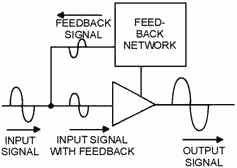
Feedback is the process of coupling a portion of the output
signal back to the input of an amplifier.
Positive (Regenerative) Feedback is provided when the feedback
signal is in phase with the input signal. Positive feedback increases the gain of
an amplifier.
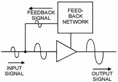
Negative (Degenerative) Feedback is provided when the feedback
signal is 180º out of phase with the input signal. Negative feedback decreases the
gain of an amplifier but improves fidelity and may increase the frequency response
of the amplifier.
1-37
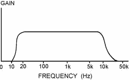
The IDEAL Frequency Response of an audio amplifier is equal
gain from 15 Hz to 20 kHz with very low gain outside of those limits.
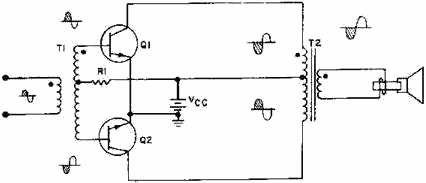
A Phase Splitter provides two output signals that are equal
in amplitude but different in phase from a single input signal. Phase splitters
are often used to provide input signals to a push-pull amplifier.
A Push-Pull Amplifier uses two transistors whose output signals
are added together to provide a larger gain (usually a power gain) than a single
transistor could provide. Push-pull amplifiers can be operated class A, class AB
or class B.
1-38
Answers to Questions Q1. Through Q33.
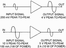
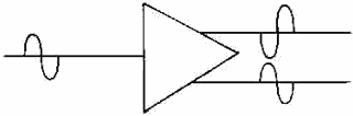
A-1. Amplification is the control of an output signal by an input signal so that
the output signal has some (or all) of the characteristics of the input signal.
The output signal is generally larger than the input signal in terms of voltage,
current, or power.
A-2. No, the input signal is unchanged, the output signal is controlled by the
input signal but does not effect the actual input signal.
A-3. To amplify the input signal to a usable level.
A-4. By function and frequency response.
A-5. An audio power amplifier.
A-6. An RF voltage amplifier.
A-7. The amount of time (in relation to the input signal) in which current flows
in the output circuit.
A-8. A, AB, B, C.
A-9. Class B operation.
A-10. The amplifier operates (and therefore uses power) for less time in class
C than in class
A. A-11. Class a operation.
A-12. To transfer energy (a signal) from one stage to another.
A-13. Direct, RC, impedance, and transformer coupling.
A-14. RC coupling.
A-15. Transformer coupling.
A-16. RC coupling.
1-39
A-17. Impedance coupling.
A-18. Equal impedance.
A-19. Lower than.
A-20. Common emitter-medium input, medium output; common base-low input, high
output; common collector-high input, low output.
A-21. Common collector.
A-22. Transformer coupling.
A-23. The process of coupling a portion of the output of a circuit back to the
circuit input.
A-24. Positive and negative or regenerative and degenerative.
A-25. Positive (regenerative) feedback.
A-26. Negative (degenerative) feedback.
A-27. Negative (degenerative) feedback.
A-28. Negative (degenerative) feedback.
A-29. a device that provides two output signals that differ in phase from a single
input signal.
A-30. a phase splitter is used to provide the input signals to a push-pull
amplifier.
A-31. a push-pull amplifier is used when high power output and good fidelity
are needed.
A-32. a push-pull amplifier provides more gain than a single transistor amplifier.
A-33. Class A, Class AB or Class B operation.
1-40
|


