|
This "Introduction to Radar" material is from the U.S. Air Force's Air University
collection of tutorials. I found it in a bin at Goodwill, bound along with a few
other sections by the Extension Course Institute including
Electronics Fundamentals
and Television Principles. This treatise on radar is the first of those sections
which will be posted here on RF Cafe. No date is included in the document, but my
guess based on the content and drawings is sometime in the late 1950's. No mention
is made of Doppler (a 1940's development), although it was used to some degree toward
the end of World War II. The existence of over-the-horizon radar (a 1960's
development) is alluded to, but not expounded upon. The "A" in the "A-scan" radar
display stands for "amplitude;" it is an oscilloscope time-based sweep. An "A-scan"
display is what the mountaintop UHF radar operators in Hawaii were monitoring when
Japanese aircraft attacked
Pearl Harbor
on December 7, 1941.
Introduction to Radar - Air University
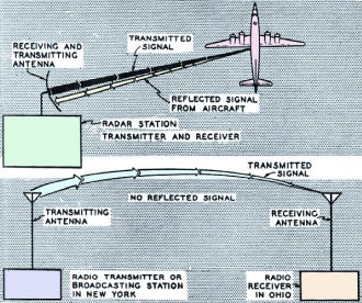
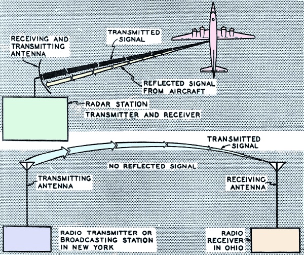
Fig. 1 - Radar and radio compared.
Before you begin the study of the physical and mathematical principles which
you as a student of electronics must understand to work successfully with electronic
equipment, you should know something about what radar can do. Not to know that would
be just like making a thorough study of gasoline engines without having any idea
how they are used in automobiles, motor boats, or airplanes.
Just as there are many different types of gasoline engines - radial, v-shaped,
in-line - there are also many types of radar sets, each designed for a special purpose
but each employing the same fundamental principles of physics, mathematics, and
electricity. Although radar uses theories which had been applied to radio and other
electronic devices before World War II, only during that war did its development
really push ahead. Today, radar is a most important application of the science of
electronics to modern warfare.
1. Radar as a Radio Device
If you are old enough to remember much about the last war, you recall the mystery,
the cloak-and-dagger atmosphere, which surrounded radar. That secrecy came about
not because radar was particularly complicated but because it had been classified
as a "secret weapon. " Actually, radar circuits are no more complicated than many
other electrical circuits, and even the newer radar sets are only refinements of
combinations of circuits which appeared in early sets. Since the basic principles
of operation are the same for all radar sets, the many various types mostly just
combine their circuits differently.
Essentially, radar is a radio device used to locate airplanes, ships, or other
objects in darkness, fog, and storms, and its kinship with radio is even emphasized
in the word "radar," which means "radio detection and ranging." When we tell you
that the simplest radar equipment is roughly equivalent to a home radio receiver
combined with a radio broadcasting station, you can see that radar is indeed a radio
device, although of course its military value far exceeds that of the ordinary radio
set. Look now at figure 1, which illustrates this comparison.
Figure 1, as you can see, shows important similarities and differences between
radar and radio. Let's see first how they are alike. One big similarity is that
both radar and radio transmit signals in much the same way. Another is that the
signals themselves are the same type of radiation - a form of electromagnetic radiation,
of which light itself is the most common example. Later on we will tell you much
more about electromagnetic radiation.
Up to here we've emphasized the similarities. Now, how about the differences?
In radar the transmitter (broadcasting station) and. receiver are in one compact
assembly, but in radio they are located many miles apart. Likewise, the radar antenna
serves as the receiving as well as the transmitting antenna, while radio uses two
antennas, possibly hundreds of miles apart. Note too that part of the transmitted
signal, called the reflected signal or echo, is returned to the radar antenna; in
radio, however, none of the transmitted signal is returned to the broadcasting station.
There are lots of other differences, but these are enough to give you an idea how
radar differs from radio. We'll go into these and the others at greater length further
on in the course.
2. Some Fundamental Principles Used in Radar
Just as you need to know the principle of internal combustion to understand a
gasoline engine, so also do you need to know the fundamental principles which radar
uses. One of the basic physical laws which apply to radar is that time is required
for an object to pass between two points in space. Similarly, it requires time for
energy, say in the form of sound waves, to pass through a given distance. Sound
waves, we know, travel at about 1,090 feet per second. This means that an observer
would be aware of an interval between the instant he sees a flash of lightning and
the instant when he hears the sound of thunder. Or an even better example in that
it covers less distance, is that of the caddy on the golf course a couple of hundred
yards away from the tee. He watches the golfer swing at the ball, but there is a
brief lapse before he hears the impact. The time interval naturally is proportional
to the distance of the flash or the golfer from the observer.
Still another example of sound waves requiring time to travel is echoes, a form
of wave reflection. If you shout toward a cliff, or some other sound-reflecting
surface, you hear your shout return from the direction of the cliff. What's happening
is that the sound waves generated by the shout travel through the air until they
strike the cliff; they are then reflected or "bounced off," some waves returning
to you. Some interval of time passes between the instant you shout and the instant
you hear the echo. Obviously, the farther you are from the reflecting surface, the
longer you'll have to wait for the echo. We've said already that sound waves travel
at 1,090 feet per second. So if you were 2,180 feet from a cliff when you shouted,
it would take four seconds for the echo to get back to you - two seconds each way.
A radar transmitter does not, of course, transmit sound waves, but it does radiate
energy in the form of radio waves, themselves electromagnetic. If these waves meet
some reflecting surface, such as an aircraft, naval vessel, or building, some of
them are reflected back to the radar station, where the receiver detects them and
indicates the presence of the reflecting object on the indicator or radar scope.
3. Properties of Radio Waves
Now that we've run over some of the fundamental principles of radar, let's get
a little more specific and look at some of the properties of radio waves. One of
their most important properties is that they may be directed into a narrow beam
by use of special constructed antennas. Light, another form of electromagnetic radiation,
may also be narrowed by the use of suitable reflectors: Every night we see this
principle at work in automobile headlights. And so antennas used in radar may be
said to serve the same function for directing radio waves into a narrow beam as
light reflectors do in narrowing light waves.
Another property of radio waves of the kind used in radar is that most surfaces
reflect them in exactly the same way as they reflect light.
And just as some surfaces reflect light better than other surfaces, so do some
materials reflect radar waves better than others.
Still a third important property is that radio waves travel with the speed of
light, in straight lines from their source.
Here you may want to know how far. Well, radar sets have been designed to transmit
radio waves well over a hundred miles, and some have been especially adapted to
bounce them off the moon.
All of these properties contribute to radar's military usefulness, but the last
two, speed and range, are the two which make radio waves particularly well suited
for target detection. Because radio waves travel so fast, an airplane flying within
range of the set would move only a negligible distance before the reflected waves
returned to the set.
But as good as radar appears to be, it isn't all gravy. One limitation is that
radar waves travel in straight lines and don't normally follow the curvature of
the earth. So radar can't "see" very far over the horizon nor under water. Not only
that, but signals reflected from clouds sometimes resemble signals reflected from
aircraft or ships and confuse new operators. The enemy too can interfere with radar;
and, as with any other complex electronic equipment, various mechanical and electrical
failures plague it at times.
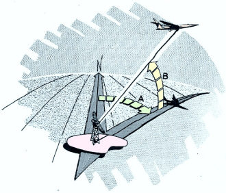
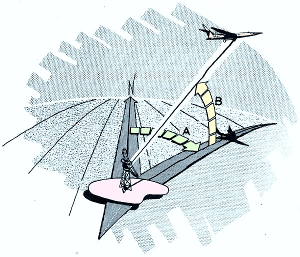
Fig. 2 - Azimuth and elevation.
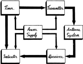
Fig. 3 - A block diagram of the six main parts of a radar set.
4. Range, Elevation, and Azimuth
We've said already that radar is fine for detecting targets, even though most
of the waves of radio energy sent out from a radar set are lost in space. You can
see why: Targets occupy such a tiny part of the air space of the universe that only
a few waves can hit anything and be reflected back to the receiver. Yet these few
are the waves we're really interested in, for they enable the operator to locate
the target - its distance away, its height, and its direction.
To pass on that information to people who need it, radar operators use three
terms borrowed from gunnery: range, elevation, azimuth. A couple of them, range
and elevation, are familiar to most of us. If you've ever hunted game, you've referred
to the effective range of your gun, meaning by that the distance your gun would
shoot accurately. Well, to radar operators, range is still distance, except to them
it means the distance the target is away from the set.
Elevation won't give most of us any trouble either. Elevation we think of as
height, and to the radar operator that's exactly what it is. The only difference
is that he expresses elevation as an angle, the angle between a line drawn from
his set to the target and a line drawn horizontally through his set in the direction
of the target.
Azimuth, though, is somewhat less familiar, and so we will define it rather carefully.
If you draw a straight line from the set pointing toward true north and then draw
another from the same point of the set to a point on the earth directly beneath
the target, the angle formed by the two lines, measured from the true north line
in a clockwise manner to the other line, is known as the azimuth angle or simply
as the azimuth of the target.
If you'll look now at figure 2, you'll see that A is the azimuth angle and B
the angle of elevation. Range, we feel, is self-explanatory.
A. The azimuth angle.
B. The elevation angle.
5. Radar Components
Let's leave range, elevation, and azimuth for awhile and see now what the main
parts of a radar set are.
Right away we observe that a radar set is more complex than a home radio set,
which detects the energy sent out by the broadcasting station and changes it into
audible sound waves. A radar set does more than that, as we've already mentioned.
Not only does it pick up radio waves but also sends them out. Then it measures the
time necessary for the radio waves to go to the target and be reflected back to
the point of transmission. To do these tasks requires more parts than are contained
in a home radio receiver and demands that most of the parts work in a certain time
relationship to each other. The six main components, or parts, of a radar set which
make this possible are the transmitter, the receiver, the indicator, the antenna,
the timer, and the power supply. Look at figure 3 and see how they are tied together.
Now you are ready to go ahead and find out what each does.
First let's talk about the radar transmitter. It's similar to a radio broadcasting
station, generating radio waves of the type for which it is constructed. However,
we must apply this comparison with care, since a commercial broadcasting station
in operation produces radio waves continuously while most radar transmitters send
out energy, radio waves, only during very short, evenly-spaced intervals of time.
It's like the difference between a steady stream of water coming out of a faucet
and a stream coming out in short, regular spurts, except in radar we're dealing
with fractions of seconds so small we can hardly conceive of them. You can see what
we mean - the energy produced during each short interval of operation, called a
pulse, may be only about one millionth of a second in duration with perhaps one
thousandth of a second between pulses. After sending out each pulse, the transmitter
is idle long enough, before sending out the next pulse, to permit the pulse to strike
a potential target and return.
When we turn to the radar receiver, we find that it performs some of the functions
of the home receiving set. Into the radar receiver comes the reflected pulses of
the transmitted energy. The reflected pulse, after traveling to a distant target
and back to the radar set, possesses such a very small portion of the energy of
the transmitted pulse that it isn't usable until its energy content has been greatly
increased. The receiver, then, does this job, amplifying, and passes the amplified
pulse on in usable form to another unit of the set. Unlike the home radio, no part
in a radar receiver produces a sound you can hear; the presence of the target is
indicated visually on a screen, similar to the screen of a television set, located
in the indicator unit.
We mentioned earlier that the single antenna of a radar set was both a sending
and receiving unit. We also gave as one of the properties of radio waves their capacity
for being concentrated in a very narrow beam. Now let's take a fast look at this
most important component of the radar set and see what it does. One of the antenna's
roles is to radiate into surrounding space the pulse of radio waves generated by
the transmitter. Moreover, by being specially designed, it can concentrate the radio
waves into a very narrow beam (its ability to do this is called directivity).
But it is always, as we just reminded you, a receiving as well as a sending unit.
If there are targets in the path of the beam - the concentration of radio waves
- they reflect the pulse of radio waves, sending an echo back to the set where it
is picked up by the antenna. That the same antenna may transmit as well as receive
is made possible by an electronic switching device which alternately connects the
antenna to the transmitter and to the receiver. You remember that there is an interval
between each transmitted pulse; during that interval, the transmitter is idle and
the antenna is free to receive any echoes that may return to the set.
We referred to the indicator a little while ago in connection with the receiver.
What the indicator does is receive the amplified pulse or echo from the receiver
and present in such a way that the radar operator can determine the range, azimuth,
and elevation of the target. Watching the television type screen of the indicator,
he observes a rapidly moving spot or line of light which moves across the screen.
As the spot or line moves, it brightens up targets. The moving light spot or line
has several different names - sweep, trace, time base, and scan. Of the various
types of scan, the two most common are the" A" scan and the "PPI" scan (PPI - Plan
Position Indicator).
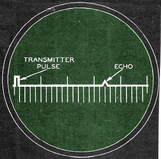
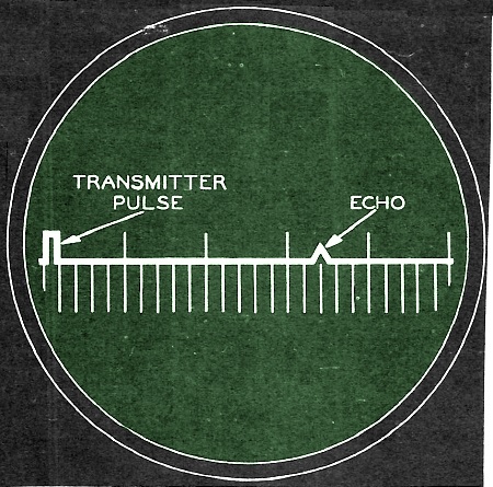
Fig. 4 - "A" scan presentation.
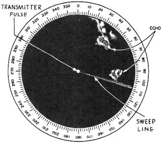
Fig. 5 - PPI-scan presentation.
Let's see what an "A" scan looks like, as it is one of the simplest types. In
figure 4, showing an "A" scan, the horizontal line is the path across the screen.
You can't help noticing the two offsets, often called" pips ," one reflecting the
transmitted pulse and the other the echo. They do the real business of the radar
set, because they enable the operator to gather his information. The set is designed
so that the pip representing the transmitted pulse always appears at the beginning
of the sweep. Besides that, the echo pip and the transmitter pip are separated from
each other on the screen by a distance proportional to the time required for the
pulse to travel to the target and return. Since the velocity of the pulse is constant
and the screen is calibrated in feet or miles, the operator can read the distance
to the target directly on the screen. On figure 4 if each mark on the sweep line
stood for one mile, the target would be seventeen miles away.
The other common type of indicator we referred to was the "PPI" scan. You should
look now at figure 5 to see how one of them works.
The PPI scan represents a map of the area being searched with the radar set.
As shown on figure 5, the transmitter pulse, represented by the dot on the center
of the screen, and the echoes from the surrounding terrain appear as bright spots
on the screen. This dot locates the radar set in relation to the target. Although
the illustration doesn't show it the screen is marked from the center to the edge
in miles or feet so that the operator can read directly the range of the target
by looking at the screen. The PPI scan also enables the operator to find out the
azimuth of a target by observing its position relative to the center of the screen.
On figure 5, for example, the azimuth of the smaller echo or target is about 90
degrees. (Azimuth, you remember is the clockwise angle between a line drawn to true
north and a line drawn to the target.) Not all sets, we should add, are exactly
alike. On some sets the top half of the screen represents the area in front of the
set; on others, however, which use a special arrangement called azimuth stabilization,
the top of the screen represents true north and the right-hand side represents east.
What about elevation? Did we just forget it? No! You find the elevation of the
target by noting how much the antenna is tilted when the echo is being received.
The next major component, the timer, is a pretty intelligent piece of machinery.
Coordinating the work of the other components, it has been called the brain of the
radar set. Suppose we try to find out how it deserved such praise.
We've noted, you recall, that the indicator measures the time required for the
pulse of radio waves to travel to the target in its path, be reflected, and return
to the radar set. To measure that interval, the indicator must be made to operate
both at the beginning of the interval and at its end: The interval begins at the
instant the transmitter generates the pulse to be radiated; it ends at the instant
the echo returns to the set. The timer then has a couple of things to do simultaneously
- (l) to cause the transmitter to generate the pulse, (2) to start the indicator
to measuring the time interval. At the end of the interval, the indicator is moved
by the returning echo pulse.
The timer can repeat its job many times per second; how many times depends upon
its design and adjustment. Because the timer can do its job so rapidly, the indicator
reproduces the moving target on its screen as a steady image. It's just like when
you go to the neighborhood movie; the projector flashes the different pictures up
there so fast you never see the rapidly recurrent flicker. This wasn't always true
of the movies, though. If you've ever seen an old news reel or "The Birth of a Nation,"
you remember the flicker. Old cameras didn't run fast enough to eliminate it. But
modern ones do, and so does the indicator of our radar set.
The last major component of a radar set which we'll discuss is the power supply.
Because the major parts of a radar set do different jobs, they require different
voltages. The power supply therefore has to convert the single voltage entering
the set into these different voltages. For example, the voltages required for heating
some vacuum tubes differ from those required for operating various motors. In turn,
these may differ greatly from those required for the relays, etc. The power supply,
we should add, does more than increase or decrease the entering voltage; it also
changes alternating current (a.c.) to direct current (d.c.).
The basic source of power, that is, the source for the entering voltage of the
set, may be the central power system of an airplane, as in airborne radar sets,
or one or more generators designed to work effectively in the particular radar installation.
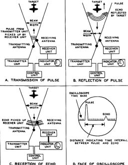
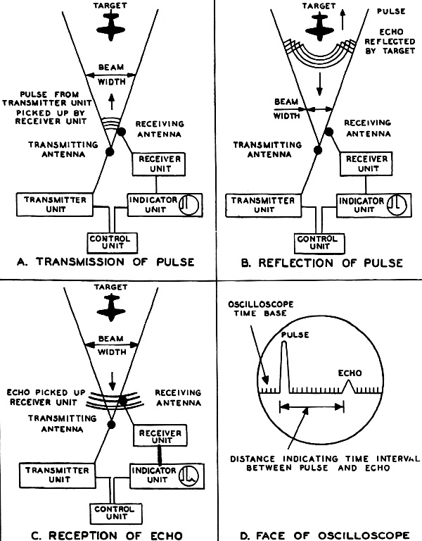
Fig. 6 - Pulse-modulated radar.
6. Equipment Used in Radar
In the preceding section we discussed the six main components of a radar set.
What we are going to do now is to tie them together as equipment. When a pulse-modulation
type of radar set is actually working, its parts operate as four important units:
a transmitter unit, a receiver unit, an indicator unit, and a control unit. We've
sketched how these units work in figure 6. (This type of drawing is called" schematic."That
means that it doesn't try to reproduce every single detail of a piece of equipment
in exact proportion. All it tries to do is to enable you, the student, to see how
one part relates to another, how the different parts work together, what they do.
They thus have this advantage over blueprints, which show exact measurements and
complete details; they let you get the idea in a short time.) Dividing them this
way doesn't mean that each of them is a separate piece of equipment. They work together
so closely and the information is gathered so rapidly (hundreds of impulses per
second, you recall) that we can't explain them as individually as we'd like to.
So if in this discussion we seem to be overlapping, we just can't help it. The parts
just work together; there's no getting away from this.
Admitting that this is true, we can first review the work of the transmitter.
(We'll also work in the receiving unit as we go along.) You remember that a transmitter
sends out radio waves in the form of pulses of extremely short duration.
These pulses, instead of being radiated in all directions from the antenna, are
directed in a narrow beam by the transmitting antenna. You can see this in the "A"
corner of figure 6. This strong transmitted pulse is received by the receiving unit
and is displayed by the indicating unit as a large vertical pip on the screen of
an electronic device known as oscilloscope. Part of the indicating unit, the oscilloscope
is pretty complex but all you need to know this far along is that it contains a
large tube, called the cathode-ray tube, similar to those in television sets. Just
as the picture in a television set appears on the large end of its cathode-ray tube,
so do the pips of a radar set appear on the large end of its cathode-ray tube.
What happens to the pulse once it leaves the transmitter? As it travels outward
into space with the speed of light, it may strike a target and be reflected by it.
You ought to glance now at the "B" part of figure 6. The reflected pulse is received
by the receiving unit and also displayed by the indicating unit as a small vertical
pip on the oscilloscope screen, as shown in the tiny circle of the indicator unit
rectangle on figure 6-C. Considered an "echo" of the transmitted pulse, this reflected
pulse is called just that in radar language.
Since the oscilloscope projects our targets so we can see them, it would be fruitful
to look at how it works in a little more detail. One ability it has strikes us immediately
- it can measure very short intervals of time by displaying the transmitted pulse
and its echo as parts of a single picture on the screen. How fast can you get?
For us to read this measurement, we have to look at the horizontal axis or line
of the screen, called the time base. And about all we have to do is look. Because
the set is designed to do some heavy calculating for us, we can read the range directly.
Here's how the set figures for us.
The distance between the pip representing the transmitted pulse and that representing
the echo, illustrated on the screen in figure 6-D, is equal to the time necessary
for the pulse to travel out to the target and be reflected back to the antenna.
Since the speed of transmission of the pulse is known to equal the speed of light,
the oscilloscope measures the time for the pulse to reach the target and be reflected
back to the antenna. This interval is then multiplied by the speed of light to give
the distance to the target and back. The range itself would of course be one-half
this distance. As we said previously, though, you don't do all this calculating;
the set does it for you.
The fourth unit we referred to was the control unit. You know that the transmitter
unit sends out pulses many times a second, and that the picture seen on the oscilloscope
screen is actually a superimposing of the pips of many pulses and their echoes on
top of one another. What the control unit does is to synchronize positively the
transmitter unit and the indicator unit so that this superimposing will take place.
Remember our discussion of azimuth? You should be able to determine the azimuth
of the target easily. Since the beam of radio energy transmitted is quite narrow,
the target will reflect an echo only if the beam is pointing at it. Thus the direction
in which the beam points when it detects a target determines the azimuth of the
target. Also, while the actual method is more complicated, you can find the angle
of elevation of aircraft by using the same principle.
Let's wind up this brief discussion of radar's equipment by adding that information
about the range, azimuth, the angle of elevation or height of the target, can be
displayed several different ways. Azimuth and angle of elevation, for instance,
can be shown on calibrated dials or meters coupled to the antenna by an appropriate
electrical system. In certain sets, range is displayed on dials or counters.
Even so, the cathode-ray tube is still the most important means of obtaining
information about a target: The other methods, such as dials, counters, or meters,
depend for their accuracy upon correct interpretation of the information upon the
face of the cathode-ray tube.
7. Early Developments in Radar
In the first part of this chapter we've introduced you to the technical background
of radar: We've explained its kinship with radio, the physical laws on which it's
based; we've defined some of the terms which the operator uses frequently, and given
you the principal units which make up a radar set. But this survey might leave you
with the impression that radar was hatched overnight into a full grown electronic
chicken. Because it wasn't, we're going to pull some sheets off the calendar and
see how the marvelous gadget called radar grew to its present stature.
Since radar is the direct descendant of radio, we're sure you won't be surprised
when we tell you that two types of radio equipment developed during the two decades
before World War II furnished the basic ideas for radar. The first was a compact
type of direction-finding equipment which uses directional antennas. The other -
you guessed it - was television, which uses the cathode-ray tube.
Let's pull a lot of sheets off our calendar now, back to 1922. For in that year
Dr. Albert M. Taylor of the Naval Research Laboratory first observed "radio echoes."
That is, he observed that a ship passing between a radio transmitter and a radio
receiver reflected some of the waves back toward the transmitter. Between 1922 and
1930, further tests proved that surface vessels hidden by smoke, fog, or darkness
could be detected by applying this principle. Because the discovery had great military
value, further experiments were strictly hush-hush. During this same period, 1922-1930,
Doctors Breit and Tuve of the Carnegie Institute published reports on the reflection
of pulse transmission from electrified layers of the upper atmosphere. You can imagine
how important that study was; From their discovery followed the application of the
principle of reflected pulse transmission to the detection of aircraft.
We didn't have far to go then. By 1930, the National Bureau of Standards Radio
Division had developed a radio set which could detect an aircraft in flight. And
finally, in 1934, further research produced a single set which could determine range,
the primary accomplishment of radar. In the same year the U.S. Navy developed radar
sets for ship-to-shore installations, and we were off.
Meanwhile, our cousins across the sea, the English, hadn't exactly been asleep
either. Robert Alexander Watson-Watt, for one, had developed what was essentially
a radar set for some experiments he was conducting with a layer of the upper atmosphere
called the ionosphere (which begins about 25 miles up). During these experiments,
"echoes" were picked up at ranges too c lose to be attributed to the ionosphere.
Finding that these echoes were caused by aircraft, and realizing the military value
of his discovery, Watson-Watt told the Air Ministry what he had found. Soon after,
in 1935, radar was first demonstrated. With slightly modified equipment placed in
a truck, the scientist was able to detect an approaching airplane and follow it
in its flight.
Unfortunately, it wasn't long before the English had to put this new information
to practical use. As Hitler moved against Austria and Czechoslovakia, it became
obvious that general war was almost inevitable, and the Air Ministry decided to
adopt this new defense against bombing. So during the years before the war, the
production of early-warning sets and their installation along the English coast
took priority over most other defense measures. With feverish haste, CH (Chain Home)
stations were erected in a net which faced Germany. When war was declared, an air
defense system using these stations was set up. By the time the Battle of Britain
began, England was ready at least in this respect.
As much progress as had been made in ground radar, not much encouragement had
been given to the development of air-borne radar equipment until, in April 1940,
the RAF Coastal Command, using air-borne equipment, sighted the missing German prison
ship, Altmark, in a Norwegian fjord. Once the Altmark incident had established its
value, however, air-borne radar was quickly adopted as night-fighter equipment.
The requirements of air-borne equipment led next to microwave radar (microwaves
are short electromagnetic waves), perhaps the greatest advancement radar made during
the war. This made the air-borne equipment even better, as microwave radar was very
accurate. It meant too that radar could now be employed for offensive bombing and
gun-laying, greatly in demand after the Allies had taken the offensive.
8. Radar as a Weapon
In the last section, we suggested the value of radar as a defensive weapon. Let's
carry that a little farther before turning to its other important characteristic,
its usefulness as an offensive weapon.
One thing that may surprise you about radar - it's more durable than you'd think.
During the Battle of Britain, stations in southeast England were bombed and their
reception interfered with, but they still did their job well. They could, for example,
warn of enemy raids hours ahead of time because they could detect German aircraft,
500 or more of them, flying in circles over Belgium or northern France as the Luftwaffe
grouped for its raids.
But the radar installations did much more than just let the cities know they
should get ready for a raid. By using the information gathered by radar, the fighter
command of the RAF was able to cripple the Luftwaffe by having fighters at the right
place at the right time. Through early-warning detection and location of enemy aircraft
by radar installations, intercepting fighters were placed directly in the path of
the approaching bombers, no matter where they attacked from. On Sunday, 15 September
1940, the Luftwaffe lost over 100 aircraft to RAF fighters guided by radar; from
that Sunday on, a black Sunday for the Germans, the daylight raids on Britain declined.
You can see, then, that radar played a mighty important part in the air battles
over Britain. Yet it was not only in defending England from the bombers of Germany
that radar played an important part; it also proved to have offensive value. The
Germans we know were aware of that importance, for crude radar equipment was found
aboard the scuttled Graff Spee. Elsewhere on the sea radar showed its worth. At
Taranto, the British navy dealt the Italian fleet a severe blow, and during landing
operations in Africa, the Americans damaged the Jean Bart. Radar, though, fully
matured with the development of the Combat Information Center as the operations
room of a warship. These CIC's used radar as their main source of information, and
in the Pacific, we won several major victories by effective use of this tactical
weapon.
At Pearl Harbor, Japanese airplanes were detected by radar when they were more
than half an hour away. To our sorrow, they were confused with some American planes
that were expected, and no one paid any attention to the warning. Later on, to be
sure, radar helped us to come back at the Japs. At Midway, use of both ship and
ground radar enabled airplanes to disperse and defeat a far superior Japanese force.
Halfway around the world, and later, the Anzio beachhead was relieved from German
night bombing by employment of new microwave gun-laying radar after all other radar
equipment had been neutralized by jamming. On the other side of the page, the use
of H2X bombing equipment on Eighth Air Force Flying Fortresses made high-precision
bombing of German targets possible even in bad weather.
So you can understand why radar successful as it proved, had been completely
accepted during the final phase of the war. As a weapon of war, we used it so often
and in so many ways that its achievements were just routine. No longer did we just
point to isolated incidents of jobs done well; we knew we had a weapon we could
depend on.
The last few months of the war continued its success story. By V-E day ground
radar control centers and navigational aids such as SHORAN (short-range navigation)
were common. Tactical air commands used radar equipment cooperatively. To this equipment
was added mortar detection equipment and moving target indicators for the proposed
invasion of Japan. But you recall that invasion never came off. Bombing by B-29's,
heavily armed with the latest in air-borne electronic aids for bombing, ROM (radio
countermeasures) equipment, and navigational aids such as LORAN (long-range navigation),
brought V-J day without costly assault.
9. Air Defense
Back in the preceding section, we touched on radar's importance in the defense
of Britain. Suppose we examine now in more detail just how radar is useful in defense.
Part of its usefulness relates to the speed of modern airplanes. Fast as they
are, if they are hostile we have to know their height, bearing, and range long before
we can see them or hear them. Similarly, fog, clouds, or smoke, either during day
or night, must not interfere with detecting enemy airplanes. So the fact that any
enemy today would have extremely fast aircraft means that your detector must be
fast too. Already we've seen that the waves which radar uses travel at the speed
of light, and so radar is plenty fast enough.
As soon as we found out we could blanket an area with radio energy so that no
object could pass through the area without our knowing it, we devised methods for
indicating the distance and direction of the object. These we've run over in earlier
sections. However, by applying known physical laws, scientists went even further:
They developed height-finding equipment accurate enough to determine the elevation
of distant aircraft to within 500 feet. The basic principle used was to place two
sets of antennas at different heights above the ground and compare the strength
of their echoes. This three-dimensional location system, with techniques for estimating
the total number of aircraft in flight, provides necessary information for establishing
defense plans.
Yet there is one other very important piece of information needed besides the
height, range, and direction: You have to know whether the approaching airplanes
are hostile or friendly. We licked this problem by arranging electrical response
or echo for our own planes different from that received from enemy airplanes. Devices
have been developed and adopted which identify friendly aircraft by automatic coded
replies which accompany the reflected echoes. Known as "IFF" (Identification, Friend,
or Foe), they are pretty remarkable inventions.
What ground radar can do in air defense is naturally very important. Once, however,
hostile aircraft have been detected, we need to send interceptors up to attack them.
These interceptors need miniature radar stations to aid them in finding and firing
on the enemy, even in clouds or at night. Since this equipment must fit into a small
airplane, it must be little and its antennas must not project and thus reduce air
speed. Another consideration is that the pilot is going to have his hands full flying
the airplane and fighting and can't take time for complicated adjustments and calculations.
So you see the air-borne set in a fighter plane must be both small and simple.
In our early fighter radar, pilots temporarily lost night vision after looking
at the screen for a long period. Eventually, however, even this problem was whipped
- by reflecting the indications on the large end of the tube onto the airplane windshield
at such an angle and focused so that as the pilot looked ahead he saw a ghostly
green flow representing the radar echo. As the enemy approached, the glowing spot
increased, "growing wings" as it came within firing range. Finally, the pilot would
see the aircraft as a dark shape in the night sky, just where the green image had
appeared.
10. Later Developments in Radar
Once we found that air-borne radar would work effectively, we soon thought of
using radar as a navigation aid, of using the radar set in the plane to receive
its echoes from beacons. p>
That was just a beginning. Before long, light weight portable beacons enabled
navigators of troop carrier planes to find the unloading area in any weather. These
portable jobs, "Eurekas, " were used in the African landings.
Nor was this the end of what we could do with radar. When we began to bomb German
targets, radar type navigational equipment became very important. The GEE system,
which we won't go into here, was prepared by the British in 1942 and, along with
other pathfinder equipment, was used successfully in the great air offensive that
began with the first 1,000-plane raids.
Radar solved other problems too. The difficulty of getting adequate aircraft
warnings coverage for offensive ground actions and task forces was overcome in 1942
by Radio Set SCR-602-T1, the first of the lightweight, portable radar sets which
became standard equipment for forward areas. Take also the matter of gun-laying.
While microwave gun-laying equipment was developed during the first years of the
war, we didn't get high-accuracy and low-altitude coverage until high-powered micro-wave
aircraft warning equipment was perfected. So much information could be obtained
by using this equipment that elaborate operations rooms, called control centers,
were placed at the sets to control fighter sweeps and other operations. Ground radar
could indeed be employed for purely offensive operations.
So you can see that radar contributed greatly to our winning the last war. Because
it partly eliminated the hazards of flying in miserable weather, greatly increased
the target hits of long-range bombing missions, and increased the carrying of troops
by air and the air transport of freight, the production of radar equipment - like
paratrooper-operated beacons, LORAN, SHORAN, AND GCA (Ground Control Approach) -
was speeded as much as possible. Radar sold itself during the last war; don't ever
forget it.
11. General Uses of Radar
In the first ten sections of the chapter, we've covered a lot of territory. Now
let's sort of wrap the whole introduction to radar up in one package. p>
We've certainly talked a lot about the different kinds of jobs radar can do.
But if you stop to think, we believe you'll agree that most of them fall into one
of three big groups: either search or fire control or navigational aid.
Let's review briefly search, whose primary function is to find targets and provide
continuous information about their location. With this information, we can estimate
the situation and decide what counter-action to take. Successful search equipment
must operate over a long range, provide complete coverage of an area, and make its
information easily visible. To do this, you recall, it uses pictorial oscilloscope
sweeps such as "PPI" or type "A."
Closely related to search is fire control. Fire-control equipment provides accurate
locating information to be used in actually firing on specified targets. Certainly,
this equipment must be very accurate, and must include some mechanical or electrical
means to convert and transmit the information into fire-control computing instruments,
such as antiaircraft artillery gun directors. Range, coverage, and pictorial presentation
are not so important in this equipment since the operator doesn't need them - the
computer is the middle-man on this deal. A desirable, though not always necessary,
feature of fire control equipment is automatic tracking, the ability to keep the
gun automatically directed on the target.
The last important use of radar, as we're sure you've figured out, is to help
ships and planes navigate better. Nearly all radar equipment can do this work. Again,
what's needed is long range, complete coverage, and a good picture. Accuracy may
be essential, although how accurate depends on the specific type of aid wanted.
Radar obviously is much more than just a weapon of war; it also has a bright
peacetime future. One use you can certainly think of yourself is to help commercial
ships and planes operate more safely. Besides that, the growing up of radar has
stimulated the entire science of electronics: The vacuum tube circuits designed
for radar are capable of hundreds of new peacetime uses.
That pretty well takes care of our introduction to radar. As you study radar,
you should remember that in spite of its newness and the air of mystery which has
surrounded it, radar is primarily a radio device which uses the principle of wave
reflection to locate targets. The main parts of a radar set are the transmitter,
the receiver, the antenna, the indicator, the timer, and the power supply. Radar's
general uses are in search, fire control, and navigation.
So much for our introduction. After working out the review questions, let's turn
in our next chapter to some fundamental mathematics which you'll need before you
go much farther with radar.
Review Questions
The following questions are study aids. Your answers are not to be submitted
to the USAF Extension Course Institute for grading.
Correct answers will be found at the end of this text.
1. Name one important respect 1n which radar and radio are similar.
2. List a few of the differences which exist between radar and radio.
3. How far away is a cliff from which an echo is heard five seconds after
sound is emitted in its direction?
4. Name some properties of radio waves which make them useful for radar applications.
5. What limitations, if any, are placed on radar by the properties mentioned
in question 4?
6. Define the terms range, azimuth, and elevation.
7. List the six ma1n components or parts of a radar set.
8. What two types of scans are most commonly used in radar sets?
9. Where on the screen of the PPI does the transmitter pulse appear?
10. What outstanding development in radar during World War II greatly
increased the precision with which radar could he operated?
11. In terms of offense and defense, how did the emphasis on the general
uses of radar shift during World War II?
12. For what purposes are IFF devices used?
13. What type of equipment was the GEE system, and for what specific purpose
was it used?
14. According to use, into what three general classifications can most radar
equipment be placed?
Answers to Review Questions (* = my comments)
Chapter 1
1. One very important respect in which radar and radio are similar is that they
both use [electro*]magnetic radiation. Also, the manner in which the signals are
radiated or broadcast is quite similar.
* original manual left off the "electro" part.
2. Some of the differences which exist between radar and radio are: (1)
in radar, the transmitter and receiver are usually mounted in the same assembly
while in radio, the two may be separated by several miles; (2) in radar, the same
antenna is often used for receiving and transmitting but in radio, two antennas
are always used; (3) in radar, a portion of the transmitted signal is reflected
from a target and returned to the transmitting antenna but in radio, none of the
transmitted signal is returned to the broadcasting station.
Note: monostatic radar has
Tx and Rx in same location, bistatic radar has Tx and
Rx in separate locations.
3. Since sound waves travel approximately 1090 feet per second, the cliff
is about 2,725 feet away from the source of the sound.
4. Some properties of radar waves which are quite useful in radar applications
are: (1) radio waves travel in straight lines and at the speed of light**; (2) they
are reflected by most surfaces just as light is reflected; and (3) radio waves may
be directed into narrow beams by means of specially constructed antennas.
** the atmosphere can bend radio waves over long distances.
5. Since radio waves travel only in straight lines and, at high frequencies,
do not normally follow the curvature of the earth, reflections from targets beyond
the horizon are not usually received. Also, reflections from clouds, land masses,
and other objects sometimes resemble reflections from aircraft or ships and confuse
radar operators.
Note: actually, over-the-horizon radar exploits the phenomenon.
6. Range is the distance from a radar set to a target. Azimuth is the angle
formed by two lines, one of which is drawn from the radar set toward true north
and the other, drawn from the same point on the radar set to a point on the earth's
surface directly beneath the target. Elevation is the angle formed by two lines,
one of which is drawn from the radar set to the target and the other is the horizontal
line which passes through the radar set and a point directly beneath the target.
7. The six main parts of a radar set are the transmitter, the receiver,
the indicator, the antenna, the timer, and the power supply.
8. The two types of scans most commonly used in radar sets are the A scan and
the PPI scan.
9. On the PPI screen, the transmitter pulse always appears at the center.
10. Microwave radar was perhaps the most outstanding development in radar
during World War II and enabled airborne equipment to be operated with much
greater precision.
11. At the beginning of World War II, radar was used almost exclusively
as a defensive weapon. However, by the end of the conflict, while its use defensively
had not decreased, major emphasis was being placed upon the employment of radar
as a weapon of offense.
12. After aircraft, ships, or other targets have been located by radar, IFF devices
are used to determine whether these targets are friendly or hostile.
13. The GEE equipment was a type of radar-navigational aid which was used
specifically to guide British aircraft in the bombing of the Ruhr.
14. The uses of radar equipment can be classified into one or more of the three
following groups: (1) Search, (2) Fire Control, and (3) Navigational Aid***.
*** this include
Precision Approach Radar (PAR) used
in "blind" landings.
Posted September 30, 2022
Related Pages on RF Cafe
-
Introduction to Radar (Air University)
- Radar Equation, 2-Way
(another)
-
Radar Equation, 1-Way
-
Radar Equation, Bistatic
-
Radar Techniques - Primer (1945 QST)
- Radar
Postage Stamps
- RF Cafe Quiz #7 - Radar Principles
- AN/MPN-14 USAF Radar Shop
- AN/TPN-19 USAF Radar Shop
- EW/Radar
Handbook - Doppler Shift
- Doppler Shift Calculator
-
Identification Friend or Foe (IFF)
-
Radar Horizon / Line of Sight
- Radar Systems Vendors
-
NEETS Radar Principles
- Radar System Vendors
- Who Invented Radar?
-
Simple Modification Increases ATC Reliability
|