| - |
Matter, Energy,
and Direct Current |
| - |
Alternating Current and Transformers |
| - |
Circuit Protection, Control, and Measurement |
| - |
Electrical Conductors, Wiring Techniques,
and Schematic Reading |
| - |
Generators and Motors |
| - |
Electronic Emission, Tubes, and Power Supplies |
| - |
Solid-State Devices and Power Supplies |
| - |
Amplifiers |
| - |
Wave-Generation and Wave-Shaping Circuits |
| - |
Wave Propagation, Transmission Lines, and
Antennas |
| - |
Microwave Principles |
| - |
Modulation Principles |
| - |
Introduction to Number Systems and Logic Circuits |
| - |
- Introduction to Microelectronics |
| - |
Principles of Synchros, Servos, and Gyros |
| - |
Introduction to Test Equipment |
| - |
Radio-Frequency Communications Principles |
| - |
Radar Principles |
| - |
The Technician's Handbook, Master Glossary |
| - |
Test Methods and Practices |
| - |
Introduction to Digital Computers |
| - |
Magnetic Recording |
| - |
Introduction to Fiber Optics |
| Note: Navy Electricity and Electronics Training
Series (NEETS) content is U.S. Navy property in the public domain. |
Module 11 - Microwave Principles Pages
i,
1-1, 1-11,
1-21,
1-31,
1-41,
1-51,
1-61,
2-1,
2-11, 2-21,
2-31,
2-41,
2-51,
2-61,
3-1,
3-11,
AI-1,
Index-1,
Assignment 1,
Assignment 2
Chapter 1: Waveguide Theory and Applications
 Learning Objectives Learning Objectives
Upon completion of this chapter the student will be able to:
- Describe the development of the various types of
waveguides in terms of their advantages and disadvantages.
- Describe the physical dimensions of the various
types of waveguides and explain the effects of those dimensions on power and frequency.
- Explain the propagation of energy in waveguides in terms of electromagnetic
field theory.
- Identify the modes of operation in waveguides.
- Explain the basic input/output methods used in waveguides.
- Describe the basic principles of waveguide plumbing.
- Explain the reasons for and the methods of terminating waveguides.
- Explain the basic theory of operation and applications of directional couplers.
- Describe the basic theory of operation, construction, and applications of cavity
resonators.
- Describe the basic theory of operation of waveguide junctions.
- Explain the operation of ferrite devices in terms of their applications.
Introduction to Waveguide Theory and Applications
That portion of the electromagnetic spectrum which falls between 1000 megahertz
and 100,000 megahertz is referred to as the Microwave region. Before discussing
the principles and applications of microwave frequencies, the meaning of the term
microwave as it is used in this module must be established. On the surface, the
definition of a microwave would appear to be simple because, in electronics, the
prefix "micro" normally means a millionth part of a unit. Micro also means small,
which is a relative term, and it is used in that sense in this module. Microwave
is a term loosely applied to identify electromagnetic waves above 1000 megahertz
in frequency because of the short physical wavelengths of these frequencies. Short
wavelength energy offers distinct advantages in many applications. For instance,
excellent directivity can be obtained using relatively small antennas and low-power
transmitters. These features are ideal for use in both military and civilian radar
and communication applications. Small antennas and other small components are made
possible by microwave frequency applications. This is an important consideration
in shipboard equipment planning where space and weight are major problems. Microwave
frequency usage is especially important in the design of shipboard radar because
it makes possible the detection of smaller targets.
Microwave frequencies present special problems in transmission, generation, and
circuit design that are not encountered at lower frequencies. Conventional circuit
theory is based on voltages and currents while microwave theory is based on electromagnetic
fields. The concept of electromagnetic field interaction is not entirely new, since
electromagnetic fields form the basis of all antenna theory. However, many students
of electronics find electromagnetic field theory very difficult to visualize and
understand. This module will present the principles of microwave theory in the simplest
terms possible but many of the concepts are still somewhat difficult to thoroughly
understand. Therefore, you must realize that this module will require very careful
study for you to properly understand microwave theory. Antenna fundamentals were
covered in NEETS, Module 10, Introduction to Wave Propagation, Transmission Lines,
and Antennas.
This module will show you the solutions to problems encountered at microwave
frequencies, beginning with the transmission of microwave energy and continuing
through to waveguides in chapter 1. Later chapters will cover the theory of operation
of microwave components, circuits, and antennas. The application of these concepts
will be discussed more thoroughly in later NEETS modules on radar and communications.
Q-1. What is the region of the frequency spectrum from 1,000 MHz to 100,000 MHz
called?
Q-2. Microwave theory is based upon what concept
Waveguide Theory

Figure 1-1 - Fields confined in two directions only.

Figure 1-2 - Fields confined in all directions.

Figure 1-3 - Waveguide shapes.
The two-wire transmission line used in conventional circuits is inefficient for
transferring electromagnetic energy at microwave frequencies. At these frequencies,
energy escapes by radiation because the fields are not confined in all directions,
as illustrated in figure 1-1. Coaxial lines are more efficient than two-wire lines
for transferring electromagnetic energy because the fields are completely confined
by the conductors, as illustrated in figure 1-2.
Waveguides are the most efficient way to transfer electromagnetic energy. WAVEGUIDES
are essentially coaxial lines without center conductors. They are constructed from
conductive material and may be rectangular, circular, or elliptical in shape, as
shown in figure 1-3.
Waveguide Advantages
Waveguides have several advantages over two-wire and coaxial transmission lines.
For example, the large surface area of waveguides greatly reduces COPPER (I2R) LOSSES.
Two-wire transmission lines have large copper losses because they have a relatively
small surface area. The surface area of the outer conductor of a coaxial cable is
large, but the surface area of the inner conductor is relatively small. At microwave
frequencies, the current-carrying area of the inner conductor is restricted to a
very small layer at the surface of the conductor by an action called SKIN EFFECT.
Skin effect was discussed in NEETS, Module 10, Introduction to Wave Propagation,
Transmission Lines, and Antennas, Chapter 3. Skin effect tends to increase the effective
resistance of the conductor. Although energy transfer in coaxial cable is caused
by electromagnetic field motion, the magnitude of the field is limited by the size
of the current-carrying area of the inner conductor. The small size of the center
conductor is even further reduced by skin effect and energy transmission by coaxial
cable becomes less efficient than by waveguides. Dielectric LOSSES are also lower
in waveguides than in two-wire and coaxial transmission lines. Dielectric losses
in two-wire and coaxial lines are caused by the heating of the insulation between
the conductors. The insulation behaves as the dielectric of a capacitor formed by
the two wires of the transmission line. a voltage potential across the two wires
causes heating of the dielectric and results in a power loss. In practical applications,
the actual breakdown of the insulation between the conductors of a transmission
line is more frequently a problem than is the dielectric loss.
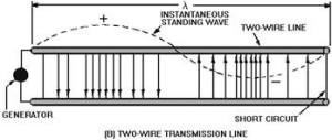
This breakdown is usually caused by stationary voltage spikes or "nodes" which
are caused by standing waves. Standing waves are stationary and occur when part
of the energy traveling down the line is reflected by an impedance mismatch with
the load. The voltage potential of the standing waves at the points of greatest
magnitude can become large enough to break down the insulation between transmission
line conductors.
The dielectric in waveguides is air, which has a much lower dielectric loss than
conventional insulating materials. However, waveguides are also subject to dielectric
breakdown caused by standing waves. Standing waves in waveguides cause arcing which
decreases the efficiency of energy transfer and can severely damage the waveguide.
Also since the electromagnetic fields are completely contained within the waveguide,
radiation losses are kept very low.

Figure 1-4 - Comparison of spacing in coaxial cable and a circular
waveguide.
Power-handling capability is another advantage of waveguides. Waveguides can
handle more power than coaxial lines of the same size because power-handling capability
is directly related to the distance between conductors. Figure 1-4 illustrates the
greater distance between conductors in a waveguide.
In view of the advantages of waveguides, you would think that waveguides should
be the only type of transmission lines used. However, waveguides have certain disadvantages
that make them practical for use only at microwave frequencies.
Waveguide Disadvantages
Physical size is the primary lower-frequency limitation of waveguides. The width
of a waveguide must be approximately a half wavelength at the frequency of the wave
to be transported. For example, a waveguide for use at 1 megahertz would be about
500 feet wide. This makes the use of waveguides at frequencies below 1000 megahertz
increasingly impractical. The lower frequency range of any system using waveguides
is limited by the physical dimensions of the waveguides.
Waveguides are difficult to install because of their rigid, hollow-pipe shape.
Special couplings at the joints are required to assure proper operation. Also, the
inside surfaces of waveguides are often plated with silver or gold to reduce skin
effect losses. These requirements increase the costs and decrease the practicality
of waveguide systems at any other than microwave frequencies.
Q-3. Why are coaxial lines more efficient at microwave frequencies than
two-wire transmission lines?
Q-4. What kind of material must be used in the construction of waveguides?
Q-5. The large surface area of a waveguide greatly reduces what type of loss
that is common in two-wire and coaxial lines?
Q-6. What causes the current-carrying area at the center conductor of a coaxial
line to be restricted to a small layer at the surface?
Q-7. What is used as a dielectric in waveguides?
Q-8. What is the primary lower-frequency limitation of waveguides?
Developing the Waveguide from Parallel Lines

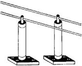
Figure 1-5 - Two-wire transmission line using ordinary insulators.

Figure 1-6 - Quarter-wave section of transmission line shorted
at one end.

Figure 1-7 - Metallic insulators on each side of a two-wire line.

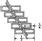
Figure 1-8 - Forming a waveguide by adding quarter-wave sections.
You may better understand the transition from ordinary transmission line concepts
to waveguide theories by considering the development of a waveguide from a two-wire
transmission line. Figure 1-5 shows a section of two-wire transmission line supported
on two insulators. At the junction with the line, the insulators must present a
very high impedance to ground for proper operation of the line. a low impedance
insulator would obviously short-circuit the line to ground, and this is what happens
at very high frequencies. Ordinary insulators display the characteristics of the
dielectric of a capacitor formed by the wire and ground. As the frequency increases,
the overall impedance decreases. a better high- frequency insulator is a quarter-wave
section of transmission line shorted at one end. Such an insulator is shown in figure
1-6. The impedance of a shorted quarter-wave section is very high at the open-end
junction with the two-wire transmission line. This type of insulator is known as
a METALLIC INSULATOR and may be placed anywhere along a two-wire line. Note that
quarter-wave sections are insulators at only one frequency. This severely limits
the bandwidth, efficiency, and application of this type of two-wire line.
Figure 1-7 shows several metallic insulators on each side of a two-wire transmission
line. As more insulators are added, each section makes contact with the next, and
a rectangular waveguide is formed. The lines become part of the walls of the waveguide,
as illustrated in figure 1-8. The energy is then conducted within the hollow waveguide
instead of along the two-wire transmission line.
The comparison of the way electromagnetic fields work on a transmission line
and in a waveguide is not exact. During the change from a two-wire line to a waveguide,
the electromagnetic field configurations also undergo many changes. These will be
discussed later in this chapter. As a result of these changes, the waveguide does
not actually operate like a two-wire line that is completely shunted by quarter-wave
sections. If it did, the use of a waveguide would be limited to a single-frequency
wavelength that was four times the length of the quarter-wave sections. In fact,
waves of this length cannot pass efficiently through waveguides. Only a small range
of frequencies of somewhat shorter wavelength (higher frequency) can pass efficiently.
As shown in figure 1-9, the widest dimension of a waveguide is called the "a"
dimension and determines the range of operating frequencies. The narrowest dimension
determines the power-handling capability of the waveguide and is called the "b"
dimension.

Figure 1-10A - Frequency effects on a waveguide for normal frequency.

Figure 1-10B - Frequency effects on a waveguide for increasing
frequency.

Figure 1-10C - Frequency effects on a waveguide for decreasing
frequency.
Note
Throughout NEETS, 1/4λ and λ/4 are both used to represent one quarter-wavelength
and are used interchangeably. Also, λ/2 and 3/2λ will be used to represent one half-wavelength
and 1 1/2 wavelengths, respectively.
Distance np is the width of the bus bar. If the overall dimensions of the waveguide
are held constant, the required length of the quarter-wave sections DECREASES as
the frequency increases. As illustrated in figure 1-10B, this causes the width of
the bus bar to INCREASE. In theory the waveguide could function at an infinite number
of frequencies higher than the designed frequency; as the length of each
quarter-wave section approaches zero, the bus bar continues to widen to fill
the available space. However, in practice, an upper frequency limit is caused by
modes of operation, which will be discussed later.

Figure 1-9 - Labeling waveguide dimensions.
If the frequency of a signal is decreased so much that two quarter-wavelengths
are longer than the wide dimension of a waveguide, energy will no longer pass through
the waveguide. This is the lower frequency limit, or CUT-ofF Frequency, of a given
waveguide. In practical applications, the wide dimension of a waveguide is usually
0.7 wavelength at the operating frequency. This allows the waveguide to handle a
small range of frequencies both above and below the operating frequency. The "b"
dimension is governed by the breakdown potential of the dielectric, which is usually
air. Dimensions ranging from 0.2 to 0.5 wavelength are common for the "b" sides
of a waveguide.
Q-9. At very high frequencies, what characteristics are displayed by ordinary
insulators?
Q-10. What type of insulator works well at very high frequencies?
Q-11. The frequency range of a waveguide is determined by what dimension?
Q-12. What happens to the bus bar dimensions of the waveguide when the frequency
is increased?
Q-13. When the frequency is decreased so that two quarter-wavelengths are longer
than the "a" (wide) dimension of the waveguide, what will happen?
Energy Propagation in Waveguides
Since energy is transferred through waveguides by electromagnetic fields, you
need a basic understanding of field theory. Both magnetic (H FIELD) and electric
field (E FIELD) are present in waveguides, and the interaction of these fields causes
energy to travel through the waveguide. This action is best understood by first
looking at the properties of the two individual fields.
E Field
An electric field exists when a difference of potential causes a stress
in the dielectric between two points. The simplest electric field is one that forms
between the plates of a capacitor when one plate is made positive compared to the
other, as shown in figure 1-11A. The stress created in the dielectric is an electric
field.

Figure 1-11A - Simple electric fields in a capacitor.

Figure 1-11B - Simple electric fields in a two-wire transmission
line.
Electric fields are represented by arrows that point from the positive toward
the negative potential. The number of arrows shows the relative strength of the
field. In figure 1-11A, for example, evenly spaced arrows indicate the field is
evenly distributed. For ease of explanation, the electric field is abbreviated E
field, and the lines of stress are called E lines.
...Pages 1-11 through 1-20
Related Pages on RF Cafe
Posted July 1, 2021
|


 Learning Objectives


