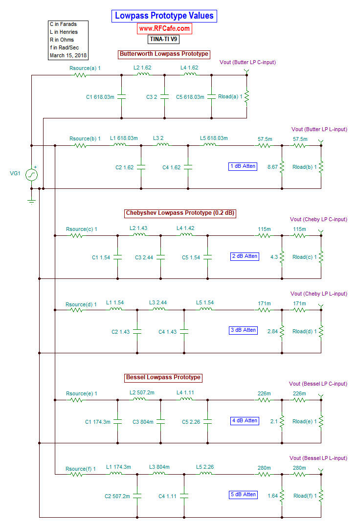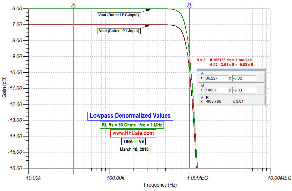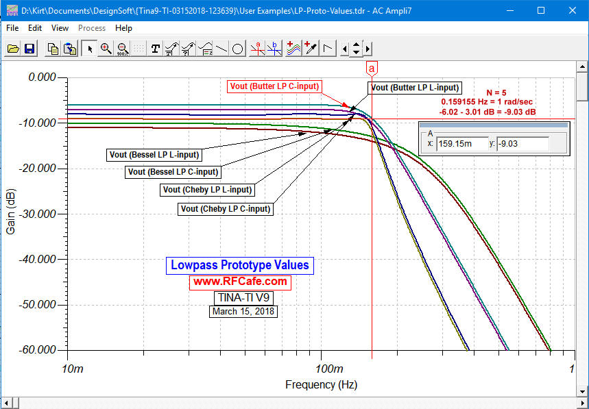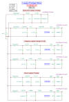
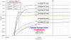
Lowpass Filters (above)
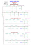
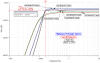
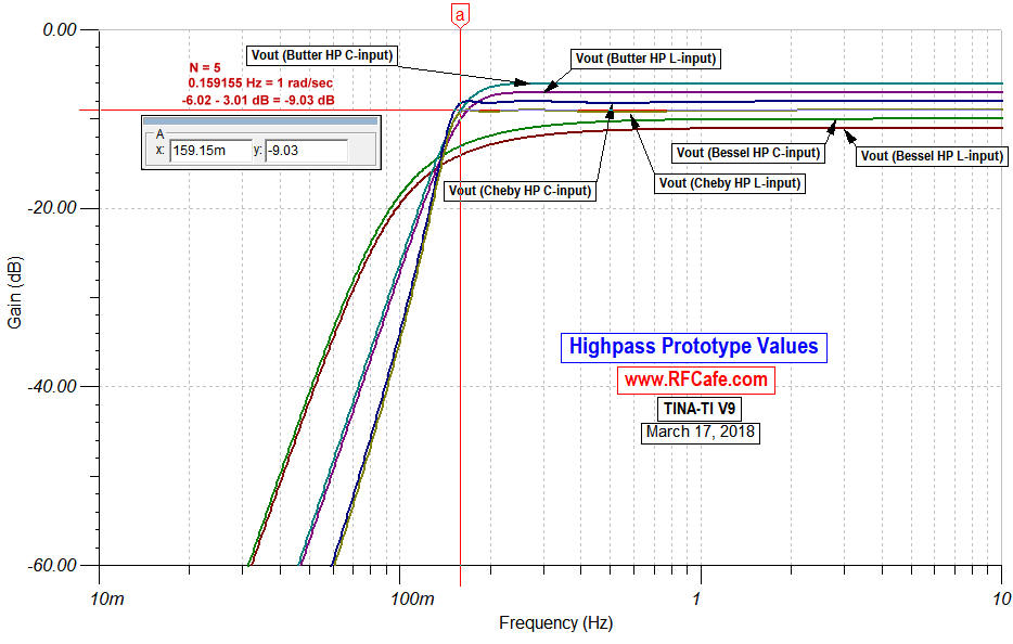
Highpass Filters (above)
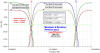

Bandpass and Bandstop Filters (above)
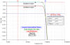
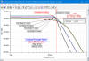
Butterworth poles lie along a circle and are spaced at equal angular distances around
a circle. It is designed to have a frequency response which is as flat as mathematically
possible in the passband, and is often referred to as a 'maximally flat magnitude' filter.
Prototype value real and imaginary pole locations (ω=1 at the 3 dB cutoff point) for
Butterworth filters are presented in the table below.
The Butterworth type filter was first described by the British engineer Stephen Butterworth
in his paper "On the Theory of Filter Amplifiers", Wireless Engineer, vol. 7, 1930, pp. 536-541.
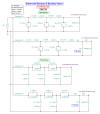
The table below lists prototype element values for the normalized lowpass function,
which assumes a cutoff frequency of 1 rad/sec and source and load impedances of 1 Ω.
Either an input capacitor (top title line in table)
or an input inductor (bottom title line in table) can
be used.
Convert Butterworth prototype values to other cutoff frequencies, impedances, and
to highpass, bandpass or bandstop using denormalization equations. Complex poles are here.
 Capacitor Input
|
Inductor Input
|
| |
| 2.000 |
|
|
|
|
|
|
|
|
|
| 1.41421 |
1.41421 |
|
|
|
|
|
|
|
|
| 1.00000 |
2.00000 |
1.00000 |
|
|
|
|
|
|
|
| 0.76537 |
1.84776 |
1.84776 |
0.76537 |
|
|
|
|
|
|
| 0.61803 |
1.61803 |
2.00000 |
1.61803 |
0.61803 |
|
|
|
|
|
| 0.51764 |
1.41421 |
1.93185 |
1.93185 |
1.41421 |
0.51764 |
|
|
|
|
| 0.44504 |
1.24698 |
1.80194 |
2.00000 |
1.80194 |
1.24698 |
0.44504 |
|
|
|
| 0.39018 |
1.11114 |
1.66294 |
1.96157 |
1.96157 |
1.66294 |
1.11114 |
0.39018 |
|
|
| 0.34730 |
1.00000 |
1.53209 |
1.87938 |
2.00000 |
1.87938 |
1.53209 |
1.00000 |
0.34730 |
|
| 0.31287 |
0.90798 |
1.41421 |
1.78201 |
1.97538 |
1.97538 |
1.78201 |
1.41421 |
0.90798 |
0.31287 |
| |
|