Electronics World articles Popular Electronics articles QST articles Radio & TV News articles Radio-Craft articles Radio-Electronics articles Short Wave Craft articles Wireless World articles Google Search of RF Cafe website Sitemap Electronics Equations Mathematics Equations Equations physics Manufacturers & distributors LinkedIn Crosswords Engineering Humor Kirt's Cogitations RF Engineering Quizzes Notable Quotes Calculators Education Engineering Magazine Articles Engineering software RF Cafe Archives Magazine Sponsor RF Cafe Sponsor Links Saturday Evening Post NEETS EW Radar Handbook Microwave Museum About RF Cafe Aegis Power Systems Alliance Test Equipment Centric RF Empower RF ISOTEC Reactel RF Connector Technology San Francisco Circuits Anritsu Amplifier Solutions Anatech Electronics Axiom Test Equipment Conduct RF Copper Mountain Technologies Exodus Advanced Communications Innovative Power Products KR Filters LadyBug Technologies Rigol TotalTemp Technologies Werbel Microwave Windfreak Technologies Wireless Telecom Group Withwave RF Cafe Software Resources Vintage Magazines RF Cafe Software WhoIs entry for RF Cafe.com Thank you for visiting RF Cafe!
Windfreak Technologies Frequency Synthesizers - RF Cafe

Copper Mountain Technologies (VNA) - RF Cafe

Anatech Electronics RF Microwave Filters - RF Cafe

Please Support RF Cafe by purchasing my  ridiculously low-priced products, all of which I created.

RF Cascade Workbook for Excel

RF & Electronics Symbols for Visio

RF & Electronics Symbols for Office

RF & Electronics Stencils for Visio

RF Workbench

T-Shirts, Mugs, Cups, Ball Caps, Mouse Pads

These Are Available for Free

Espresso Engineering Workbook™

Smith Chart™ for Excel

Anritsu Test Equipment - RF Cafe

Filter Prototype Denormalization

Simulations of Normalized and Denormalized LP, HP, BP, and BS Filters

Prototype Lowpass Filter Schematics (Butterworth, Chebyshev, Bessel) - RF Cafe

Lowpass Filters

(above)

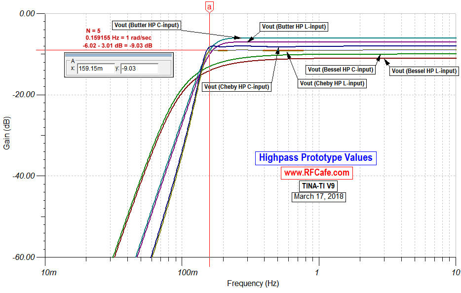
Highpass Filters

(above)

Bandpass and Bandstop Filters

(above)

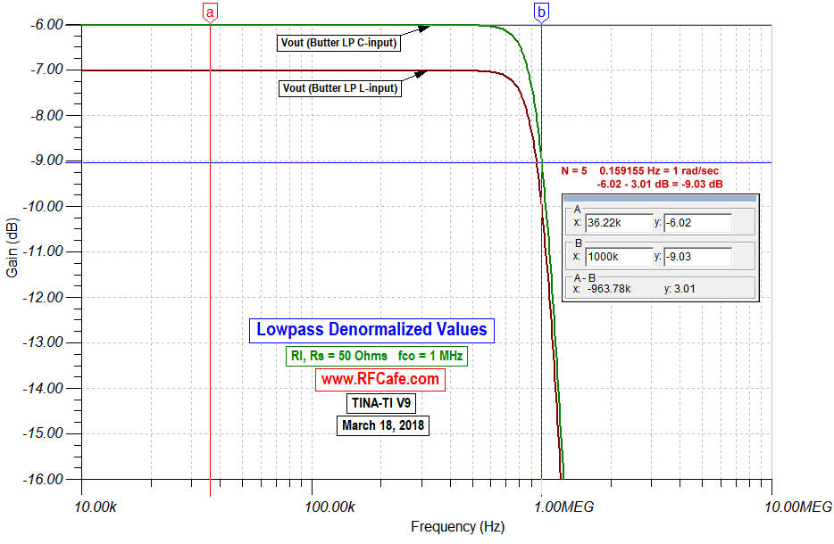
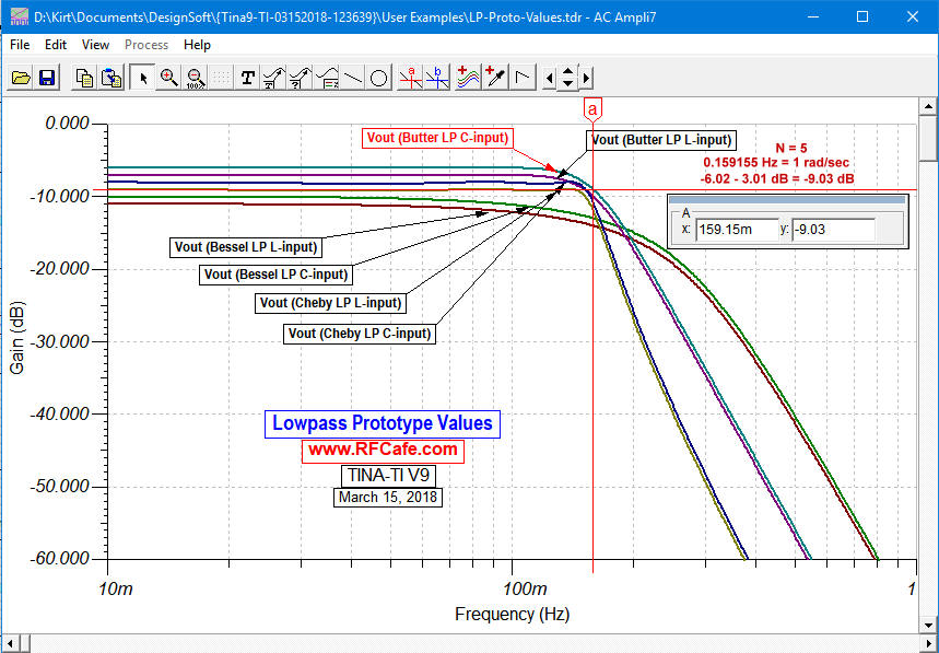
This entire page has been reworked to make the denormalization of prototype lowpass filter component values much easier to understand. I have received numerous questions about the process over the years, particularly regarding the swapping of capacitor and inductor values for highpass transformations. Bandpass and bandstop transformations can be equally confusing. The original page pretty much regurgitated the type of presentation made by many textbooks, but this new format should make amply clear the transformation from normalized lowpass component values (1 rad/sec cutoff, 1 Ω source & load impedance) to denormalized values for any frequency and source/load impedance. My reference is "Filter Design," by Steve Winder.

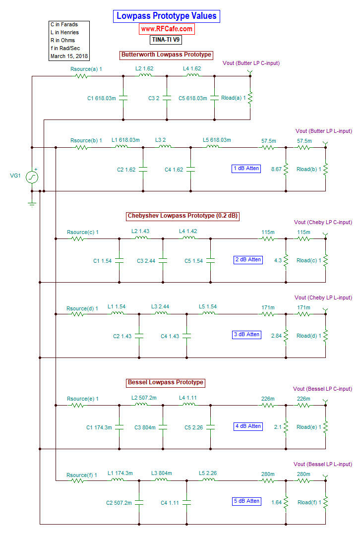
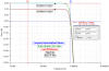
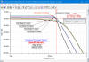
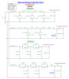
Texas Instruments' TINA circuit simulator (free download) was used with calculated component values to assure correctness. 
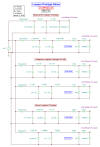
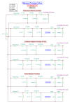
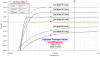
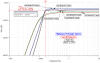
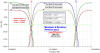
See schematics and plots to the right. Note that attenuators were used in 1 dB increments to make plots for individual circuits distinguishable.

My graphic is specifically for when the source and load impedance are equal and purely resistive (R ± j0), which is by far the most typical case. You will need to find another source for unequal and/or reactive source/load impedances. Butterworth prototype values are used in the example, but you can also get them for Chebyshev and Bessel.

Filter Prototype Denormalization Equations Formulas - RF Cafe


Posted March 31, 2018

Anritsu Test Equipment - RF Cafe
Innovative Power Products Passive RF Products - RF Cafe

KR Electronics (RF Filters) - RF Cafe

Windfreak Technologies Frequency Synthesizers - RF Cafe