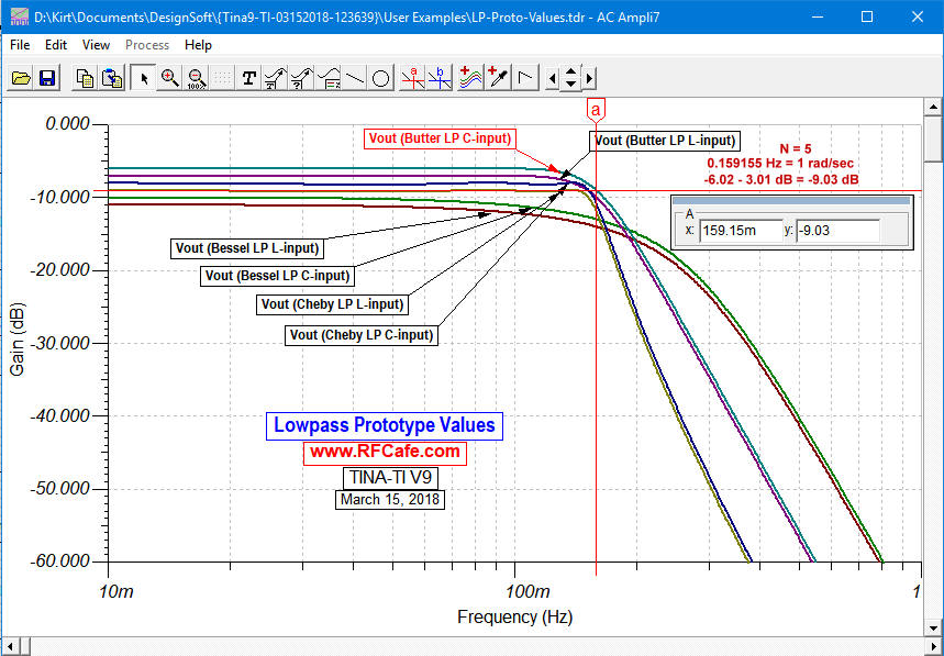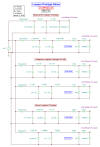
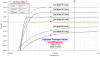
Lowpass Filters (above)
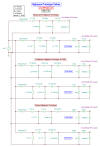
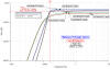
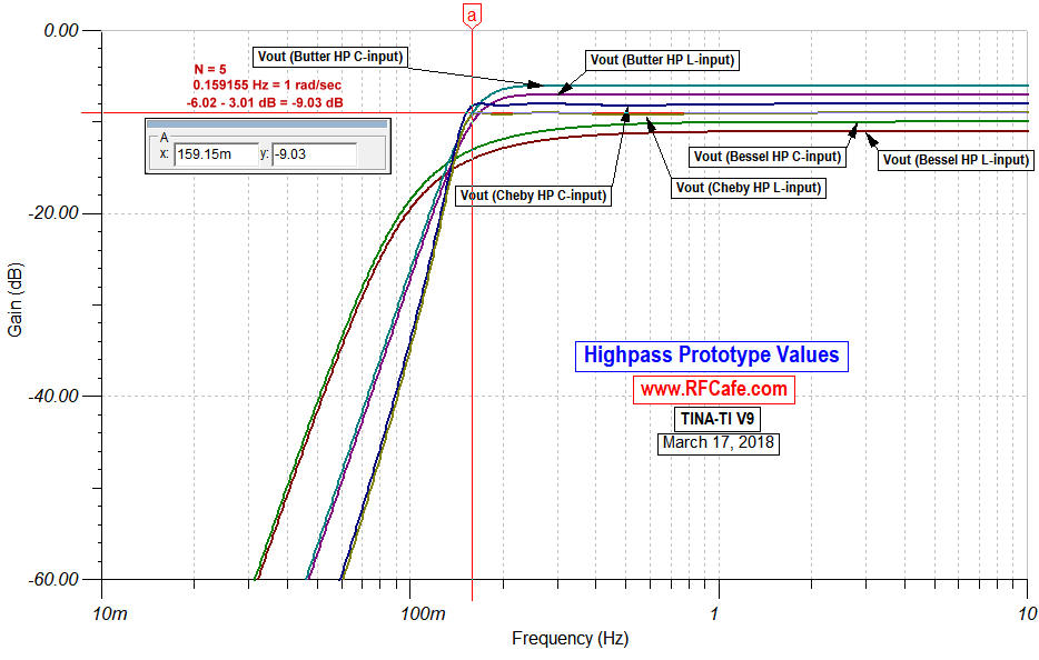
Highpass Filters (above)
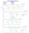
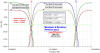

Bandpass and Bandstop Filters (above)
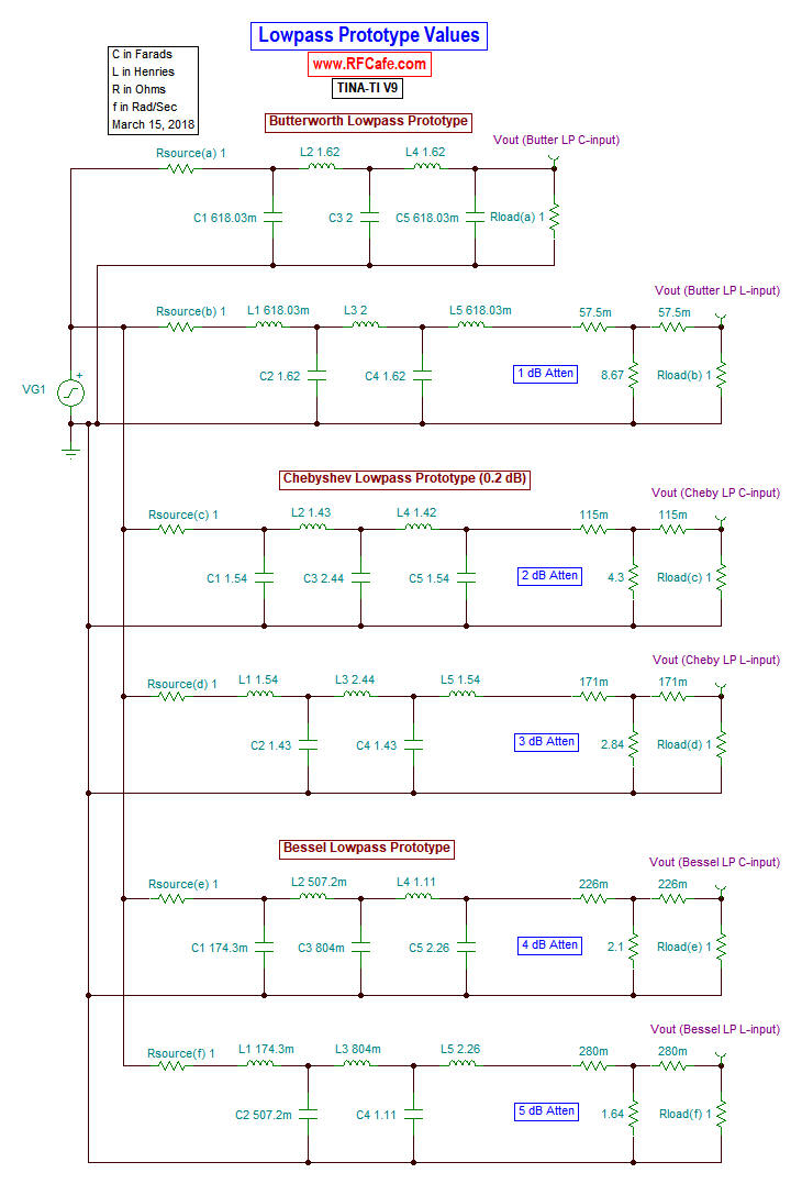
The table below lists prototype element values for the normalized lowpass function,
which assumes a cutoff frequency of 1 rad/sec and source and load impedances of 1 Ω.
Either an input capacitor (top title line in table)
or an input inductor (bottom title line in table) can
be used. Note that for even order filters, the 0 Hz (DC) insertion loss is equal to the
ripple value.
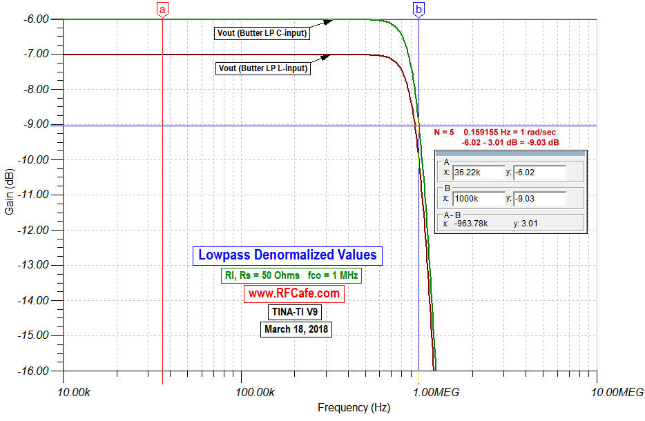
Convert values to other cutoff frequencies, impedances, and to highpass, bandpass
or bandstop using denormalization equations. Complex poles are here.
 Capacitor Input
|
Inductor Input
|
* Note: In the tables below of normalized Chebyshev filter
components values, the right-most column is labeled "RLoad." This is necessary
because even-order Chebyshev filters are not realizable when the source and termination
impedances are exactly equal. A scaling factor is included for the termination impedance
as shown.
Normalized Chebyshev element values, 0.01 dB ripple*
| |
| 0.4489 |
0.4078 |
|
|
|
|
|
|
|
0.9085 |
| 0.6292 |
0.9703 |
0.6292 |
|
|
|
|
|
|
1 |
| 0.7129 |
1.2004 |
1.3213 |
0.6476 |
|
|
|
|
|
0.9085 |
| 0.7563 |
1.3049 |
1.5773 |
1.3049 |
0.7563 |
|
|
|
|
1 |
| 0.7814 |
1.3600 |
1.6897 |
1.5350 |
1.4970 |
0.7098 |
|
|
|
0.9085 |
| 0.7970 |
1.3924 |
1.7481 |
1.6331 |
1.7481 |
1.3924 |
0.7970 |
|
|
1 |
| 0.8073 |
1.4131 |
1.7824 |
1.6833 |
1.8529 |
1.6193 |
1.5555 |
0.7334 |
|
0.9085 |
| 0.8145 |
1.4271 |
1.8044 |
1.7125 |
1.9058 |
1.7125 |
1.8044 |
1.4271 |
0.8145 |
1 |
| |
Normalized Chebyshev element values, 0.1 dB ripple*
| |
| 0.8431 |
0.6220 |
|
|
|
|
|
|
|
0.7378 |
| 1.0316 |
1.1474 |
1.0316 |
|
|
|
|
|
|
1 |
| 1.1088 |
1.3062 |
1.7704 |
0.8181 |
|
|
|
|
|
0.7378 |
| 1.1468 |
1.3712 |
1.9750 |
1.3712 |
1.1468 |
|
|
|
|
1 |
| 1.1681 |
1.4040 |
2.0562 |
1.5171 |
1.9029 |
0.8618 |
|
|
|
0.7378 |
| 1.1812 |
1.4228 |
2.0967 |
1.5734 |
2.0967 |
1.4228 |
1.1812 |
|
|
1 |
| 1.1898 |
1.4346 |
2.1199 |
1.6010 |
2.1700 |
1.5641 |
1.9445 |
0.8778 |
|
0.7378 |
| 1.1957 |
1.4426 |
2.1346 |
1.6167 |
2.2054 |
1.6167 |
2.1346 |
1.4426 |
1.1957 |
1 |
| |
Normalized Chebyshev element values, 0.20 dB ripple*
| |
| 1.0379 |
0.6746 |
|
|
|
|
|
|
|
0.6499 |
| 1.2276 |
1.1525 |
1.2276 |
|
|
|
|
|
|
1 |
| 1.3029 |
1.2844 |
1.9762 |
0.8468 |
|
|
|
|
|
0.6499 |
| 1.3395 |
1.3370 |
2.1661 |
1.3370 |
1.3395 |
|
|
|
|
1 |
| 1.3598 |
1.3632 |
2.2395 |
1.4556 |
2.0974 |
0.8838 |
|
|
|
0.6499 |
| 1.3723 |
1.3782 |
2.2757 |
1.5002 |
2.2757 |
1.3782 |
1.3723 |
|
|
1 |
| 1.3804 |
1.3876 |
2.2964 |
1.5218 |
2.3414 |
1.4925 |
2.1349 |
0.8972 |
|
0.6499 |
| 1.3861 |
1.3939 |
2.3094 |
1.5340 |
2.3728 |
1.5340 |
2.3094 |
1.3939 |
1.3861 |
1 |
| |
Normalized Chebyshev element values, 0.5 dB ripple*
| |
| 1.4029 |
0.7071 |
|
|
|
|
|
|
|
0.5040 |
| 1.5963 |
1.0967 |
1.5963 |
|
|
|
|
|
|
1 |
| 1.6704 |
1.1926 |
2.3662 |
0.8419 |
|
|
|
|
|
0.5040 |
| 1.7058 |
1.2296 |
2.5409 |
1.2296 |
1.7058 |
|
|
|
|
1 |
| 1.7254 |
1.2478 |
2.6064 |
1.3136 |
2.4759 |
0.8696 |
|
|
|
0.5040 |
| 1.7373 |
1.2582 |
2.6383 |
1.3443 |
2.6383 |
1.2582 |
1.7373 |
|
|
1 |
| 1.7451 |
1.2647 |
2.6565 |
1.3590 |
2.6965 |
1.3389 |
2.5093 |
0.8795 |
|
0.5040 |
| 1.7505 |
1.2690 |
2.6678 |
1.3673 |
2.7240 |
1.3673 |
2.6678 |
1.2690 |
1.7505 |
1 |
| |
|