[Go to TOC]
Module 1 - Introduction to Matter, Energy, and Direct Current
Pages i,
1-1,
1-11,
1-21,
1-31,
1-41,
1-51,
1-61,
2-1,
2-11,
2-21,
3-1,
3-11,
3-21,
3-31,
3-41,
3-51,
3-61,
3-71,
3-81,
3-91,
3-101,
3-111,
3-121, Appendix
I,
II,
III,
IV,
V,
Index
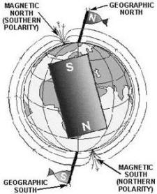
The NORTH POLE, or north seeking pole, a magnet freely suspended on a string always
points toward the north geographical pole.
The LIKE POLES magnets repel each other, while
the unlike poles attract each other.
1-51
WEBER'S THEORY of MAGNETIsM assumes that all magnetic material is made up magnetic
molecules which, if lined up in north to south pole order, will be a magnet. If not lined up, the magnetic fields
about the molecules will neutralize each other and no magnetic effect will be noted.
The DOMAIN THEORY of MAGNETIsM states that if the electrons the atoms in a material spin
more in one direction than in the other, the material will become magnetized.
A Magnetic FIELD is said to exist in the space surrounding a magnet.
1-52
Magnetic Lines of forCE are imaginary lines used to describe the patterns the magnetic
field about a magnet. These lines are assumed to flow externally from the north pole and into the south pole.
Magnetic Flux is the total number magnetic lines force leaving or entering the pole a magnet.
1-53
Flux DENSITY is the number flux lines per unit area.
FIELD INTENSITY
or the intensity a magnetic field is directly related to the magnetic force exerted by the field.
The
INTENSITY ATTRACTION/REPULSION between magnetic poles may be described by a law almost identical
to Coulomb's Law Charged Bodies, that is, the force between two poles is directly proportional to the product the
pole strengths and inversely proportional to the square the distance between the poles.
Magnetic
SHIELDING can be accomplished by placing a cast iron shield around the object to be protected, thus directing
the lines force around the object.
1-54
MAGNETS are ClassIFIED by SHAPE and include the bar magnet, the horseshoe magnet, and the
ring magnet. The ring magnet is used in computer memory circuits; the horseshoe magnet in some meter circuits.
ENERGY may be defined as the ability to do work.
The COULOMB (C)
is the basic unit used to indicate an electrical charge. One coulomb is equal to a charge 6.28 x 10¹⁸ electrons.
When one coulomb charge exists between two bodies, the electromotive force (or voltage) is one volt.
Voltage is measured as the difference potential two charges interest.
Voltage MEASUREMENTS
may be expressed in the following units: volts (V), kilovolts (kV), millivolts (mV), or microvolts (μV).
For example:
1 kV = 1,000 V
1 mV = 0.001 V
1 V = 0.000001 V
Methods of PRODUCING a Voltage include:
1. Friction
2. Pressure (piezoelectricity)
1-55
3. Heat (thermoelectricity)
1-56
4. Light (photoelectricity)
5. Chemical action (battery)
1-57
6. Magnetism (electromagnetic induction generator)
ELECTROMagnetic INDUCTION GENERATOR
To produce voltage by use magnetism, three conditions must be met: There must be a CONDUCTOR in which the voltage
will be produced; there must be a Magnetic FIELD in the conductor's vicinity; and there must be relative motion
between the field and conductor. When these conditions are met, electrons WITHIN The CONDUCTOR are propelled in
one direction or another, creating an electromotive force, or voltage.
1-58
ELECTRON CURRENT is based on the assumption that electron current flow is from negative
to positive through a circuit.
An ELECTRIC CURRENT is a directed movement electrons in a
conductor or circuit.
The Ampere is the basic unit used to indicate an electric current.
A current one ampere is said to flow when one coulomb charge (6.28 x 10¹⁸ electrons) passes a given point
in one second time. Current measurements may be expressed in the following units: ampere (A), milliampere (mA),
and microampere (μA). Current in a circuit increases in direct proportion to the voltage (emf) applied across the
circuit.
Resistance is the opposition to current. The ohm is the basic unit resistance and
is represented by the Greek letter omega (Ω). a conductor is said to have one ohm resistance when an emf one volt
causes one ampere current to flow in the conductor. Resistance may be expressed in the following units: ohm (Ω),
kilohm (kΩ), and megohms (MΩ). For example, 1,000,000 Ω = 1,000 kΩ = 1 MΩ.
The Resistance
of a MATERIAL is determined by the type, the physical dimensions, and the temperature the material that
is,
1. a good conductor contains an abundance free electrons.
2. As the cross-sectional
area a given conductor is increased, the resistance will decrease.
3. As the length a conductor is
increased, the resistance will increase.
4. In a material having a positive temperature coefficient,
the resistance will increase as the temperature is increased.
The CONDUCTANCE of a MATERIAL
is the reciprocal resistance.
The UNIT of CONDUCTANCE is the mho and the symbol is V. G
or S.
The Resistor is manufactured to provide a specific value resistance.
1-59
The CARBON Resistor is made carbon, with fillers and binders blended in to control
the ohmic value.
The Resistance of a WireWOUND Resistor is determined by the metal content the wire and
the wire's length. Wirewound resistors may be tapped so two or more different voltage values may be taken f the
same resistor.
1-60
| - |
Matter, Energy,
and Direct Current |
| - |
Alternating Current and Transformers |
| - |
Circuit Protection, Control, and Measurement |
| - |
Electrical Conductors, Wiring Techniques,
and Schematic Reading |
| - |
Generators and Motors |
| - |
Electronic Emission, Tubes, and Power Supplies |
| - |
Solid-State Devices and Power Supplies |
| - |
Amplifiers |
| - |
Wave-Generation and Wave-Shaping Circuits |
| - |
Wave Propagation, Transmission Lines, and
Antennas |
| - |
Microwave Principles |
| - |
Modulation Principles |
| - |
Introduction to Number Systems and Logic Circuits |
| - |
- Introduction to Microelectronics |
| - |
Principles of Synchros, Servos, and Gyros |
| - |
Introduction to Test Equipment |
| - |
Radio-Frequency Communications Principles |
| - |
Radar Principles |
| - |
The Technician's Handbook, Master Glossary |
| - |
Test Methods and Practices |
| - |
Introduction to Digital Computers |
| - |
Magnetic Recording |
| - |
Introduction to Fiber Optics |
| Note: Navy Electricity and Electronics Training
Series (NEETS) content is U.S. Navy property in the public domain. |