Module 1 - Introduction to Matter, Energy, and Direct Current
Pages i,
1-1,
1-11,
1-21,
1-31,
1-41,
1-51,
1-61,
2-1,
2-11,
2-21,
3-1,
3-11,
3-21,
3-31,
3-41,
3-51,
3-61,
3-71,
3-81,
3-91,
3-101,
3-111,
3-121, Appendix
I,
II,
III,
IV,
V,
Index
Solution:

Since R3 = R4 = R5 and the voltage across each branch is the same:

Solving for total resistance. Given:

3-71
Solution:
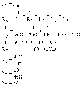
An alternate method for solving for RT can be used. By observation, you can see that R3, R 4, and R5 are
equal ohmic value. Therefore an equivalent resistor can be substituted for these three resistors in solving for
total resistance.
Given:

Solution:

The circuit can now be redrawn using a resistor labeled Reqi in place R3, R4, and R5 as shown in
figure 3-51.
3-72

Figure 3-51. - First equivalent parallel circuit.
An equivalent resistor can be calculated and substituted for R1 and R2 by use the product over the sum
formula.
Given:

Solution:
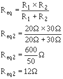
The circuit is now redrawn again using a resistor labeled Req2 in place R1 and R2 as shown in figure
3-52.
3-73
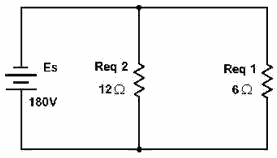
Figure 3-52. - Second equivalent parallel circuit.
You are now left with two resistors in parallel. The product over the sum method can now be used to solve
for total resistance.
Given:

Solution:
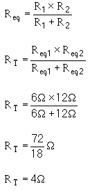
This agrees with the solution found by using the general formula for solving for resistors in parallel.
The circuit can now be redrawn as shown in figure 3-53 and total current can be calculated.
3-74
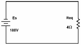
Figure 3-53. - Parallel circuit redrawn to final equivalent circuit.
Given:

Solution:

This solution can be checked by using the values already calculated for the branch currents. Given:

Solution:

3-75
Now that total current is known, the next logical step is to find total power. Given:

Solution:

Solving for the power in each branch. Given:

Solution:
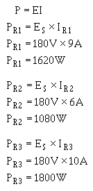
Since 1R3 = 1R4 = 1R5 then, PR3 = PR4 = PR5 = 1800 W. The previous calculation for total power can now be
checked.
3-76
Given:

Solution:

Q39. What term identifies a single resistor that represents total resistance a complex circuit?
Q40. The total power in both series and parallel circuits is computed with the formula: PT = P1 + P2 + P3 +
...Pn. Why can this formula be used for both series and parallel circuits?
Q41. a circuit consists
three resistors connected in parallel across a voltage source. R1 = 40 , R2 = 30 Ω , R3 = 40 Ω , and PR3 = 360
watts. Solve for RT, ES and 1R2. (Hint: Draw and label the circuit first.)
Series-PARALLEL DC Circuits
In the preceding discussions, series and parallel dc circuits have been considered separately. The
technician will encounter circuits consisting both series and parallel elements. a circuit this type is referred
to as a Combination Circuit. Solving for the quantities and elements in a combination circuit is simply a matter
applying the laws and rules discussed up to this point.
SOLVING Combination-Circuit PROBLEMS
The basic technique used for solving dc combination-circuit problems is the use equivalent circuits. To simplify a
complex circuit to a simple circuit containing only one load, equivalent circuits are substituted (on paper) for
the complex circuit they represent. To demonstrate the method used to solve combination circuit problems, the
network shown in figure 3-54(A) will be used to calculate various circuit quantities, such as resistance, current,
voltage, and power.
3-77
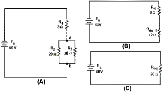
Figure 3-54. - Example combination circuit.
Examination the circuit shows that the only quantity that can be computed with the given information is
the equivalent resistance R2 and R3.
Given:

Solution:
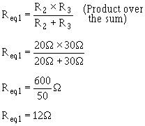
Now that the equivalent resistance for R2 and R3 has been calculated, the circuit can be redrawn as a
series circuit as shown in figure 3-54(B).
3-78
The equivalent resistance this circuit (total resistance) can now be calculated. Given:

Solution:
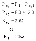
The original circuit can be redrawn with a single resistor that represents the equivalent resistance the
entire circuit as shown in figure 3-54(C).
To find total current in the circuit: Given:

Solution:
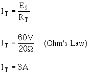
To find total power in the circuit:
Given:

3-79
Solution:

To find the voltage dropped across R1, R2 , and R3 , refer to figure 3-54(B). Req1 represents the
parallel network R2 and R3. Since the voltage across each branch a parallel circuit is equal, the voltage across
Req1 (Eeq1) will be equal to the voltage across R2 (ER2) and also equal to the voltage across R3 (ER3).
Given:

Solution:
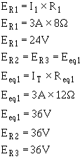
To find power used by R1: Given:

Solution:

3-80
| - |
Matter, Energy,
and Direct Current |
| - |
Alternating Current and Transformers |
| - |
Circuit Protection, Control, and Measurement |
| - |
Electrical Conductors, Wiring Techniques,
and Schematic Reading |
| - |
Generators and Motors |
| - |
Electronic Emission, Tubes, and Power Supplies |
| - |
Solid-State Devices and Power Supplies |
| - |
Amplifiers |
| - |
Wave-Generation and Wave-Shaping Circuits |
| - |
Wave Propagation, Transmission Lines, and
Antennas |
| - |
Microwave Principles |
| - |
Modulation Principles |
| - |
Introduction to Number Systems and Logic Circuits |
| - |
- Introduction to Microelectronics |
| - |
Principles of Synchros, Servos, and Gyros |
| - |
Introduction to Test Equipment |
| - |
Radio-Frequency Communications Principles |
| - |
Radar Principles |
| - |
The Technician's Handbook, Master Glossary |
| - |
Test Methods and Practices |
| - |
Introduction to Digital Computers |
| - |
Magnetic Recording |
| - |
Introduction to Fiber Optics |
| Note: Navy Electricity and Electronics Training
Series (NEETS) content is U.S. Navy property in the public domain. |


