Module 6 - Introduction to Electronic Emission, Tubes, and Power
Supplies
Pages i,
1-1,
1-11,
1-21,
1-31,
1-41,
1-51,
2-1,
2-11,
2-21,
2-31,
3-1,
3-11,
3-21,
3-31,
3-41,
3-51, AI-1, Index
Tube 2:

Thus, you can expect twice the change in plate voltage from tube 2 as from tube 1 for the same input
voltage. Therefore, tube 2 will have twice the gain of tube 1. Transconductance
Transconductance is a measure of the change in plate current to a change in grid voltage, with plate voltage held
constant. The unit for conductance is the mho (siemens), pronounced "moe." Transconductance is normally expressed
in either micromhos or millimhos. Mathematically, transconductance is expressed by the formula:

Examine figure 1-28, views a and B, again. In view A, the input voltage is +1 volt. At +1 volt Eg, the
plate current is equal to 1 milliampere, with a plate voltage of 250 volts. In view B, the input voltage (Eg) is
raised to +3 volts. ¨( g, as before, is equal to 2 volts. This increase in grid voltage causes plate current to
increase to 2 milliamperes. The change in plate current (Ip) is then equal to 1 milliampere. Thus,
transconductance (gm) is equal to:

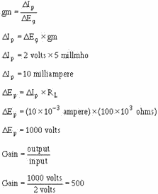
Remember that the voltage gain of a circuit is measured by the ratio of the change in plate voltage to
the change in grid voltage. Because plate voltage is developed across a resistor, the more current varies with a
given input signal, the greater will be the output (E = I × R). If you have two tubes, one with a gm of 500 mhos
and the other with a gm of 500 µmhos, you can estimate the relative gain of these two tubes. Assume that the
circuit in which you wish to use one of these tubes has a load resistor of 100 kohms and that Eg will be 2 volts.
The voltage gain of these two circuits will be:
1-41
Tube 1:
Tube 2:
1-42
As you can see, tube 2 is 10 times the amplifier that tube 1 is. Q26. The plate voltage of
a tube will vary 126 volts when a 3-volt ac signal is applied to the control grid. What is the gain of this tube?
Q27. If the mu of a tube is 85 and the signal at the control grid is 4 volts ac, the plate voltage will
vary by what amount? Q28. Transconductance is a measure of the relationship between what two factors?
Q29. a tube has a transconductance of 800 mhos and a load resistor of 50 kohms. When control grid voltage
varies by 6 volts, the plate voltage will vary by what amount? Interelectrode Capacitance
As you know, capacitance exists when two pieces of metal are separated by a dielectric. You should
also remember from your studies that a vacuum has a dielectric constant of 1. As the elements of the triode are
made of metal and are separated by a dielectric, capacitance exists between them. This capacitance is called
interelectrode capacitance, and is schematically represented in figure 1-29.
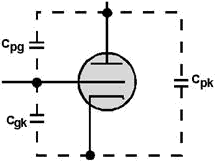
Figure 1-29. - Schematic representation of interelectrode capacitance. Notice that there are three interelectrode capacitances involved in a triode. The capacitance between
the plate and grid, designated Cpg, is the largest, because of the relatively large area of the plate, and
therefore has the greatest effect on triode operation. The grid-to-cathode capacitance is designated Ckg.
The total capacitance across the tube is designated Cpk. As we said earlier, Cpg has the greatest effect
on the tube operation. This is because this capacitance will couple part of the ac signal from the plate back to
the grid of the tube. The process of coupling the output of a circuit back to the input is called Feedback.
This feedback affects the gain of the stage. It may be desirable in some applications. In others, the effects must
be neutralized. The effects of Cpk are greater at higher frequencies where Xc is lower.
1-43
DEVELOPMENT of The TETRODE Interelectrode capacitance cannot be eliminated
from vacuum tubes, but it can be reduced. The easiest method found to reduce interelectrode capacitance is to
split the capacitance between the grid and plate (Cpg) into two capacitors connected in series. This is done by
placing an extra grid, called the SCREEN GRID, between the control grid and the plate. This is
shown in figure 1-30.
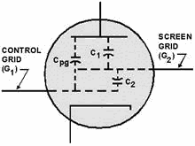
Figure 1-30. - Effect of the screen-grid on Interelectrode capacitance. Remember from your study of capacitance that connecting capacitors in series reduces the total
capacitance to a value smaller than either of the capacitors. This is mathematically summed up as follows:

The addition of the screen grid has the effect of splitting Cpg into two capacitances (C1 and C2)
connected in series. Therefore, the total interelectrode capacitance between the control grid and the plate is
greatly reduced. Operation of The Basic TETRODE Circuit Figure 1-31 depicts a
basic tetrode circuit. While the circuit may look complicated, it isn't. You are already familiar with most of the
circuit. Only three components have been added: the screen grid, the screen grid dropping resistor, and the screen
grid bypass capacitor (Csg).
1-44
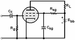
Figure 1-31. - Basic tetrode circuit. The problem now is: at what voltage and polarity should the screen grid be operated? If the screen grid
were operated at a potential that would make it negative in relation to the control grid, it would act as a
negative screen between the plate and control grid. As a result, gain would be reduced. If the screen grid were
operated at plate potential, it would draw current from the electron stream when the tube conducts. Because of
this, the value of Rsg is normally selected to cause the screen grid to be positive in relation to the control
grid, but not as positive as the plate. Despite this precaution, the screen grid still draws some current
from the electron stream. Any signal applied to the control grid will appear at the screen grid inverted by 180º
from the input signal. This is undesirable, as it reduces the gain of the tube. Consider the effect if the control
grid goes positive. Conduction through the tube increases, and since the screen grid is in the electron stream, it
will draw some current. This causes the screen grid to go toward negative potential (less positive). The effect
then, is to place a negative-going electrode between the plate and positive-going control grid. The plate becomes
partially screened by the negative-going screen grid, and again, gain will decrease. Because the signal at the
screen grid is always 180º out of phase with the control grid, its effect will always be to oppose the effect of
the control grid. To overcome this, a bypass capacitor (Csg) is connected between the screen grid and
ground. The addition of this capacitor will shunt, or pass, the ac variations on the screen grid to ground while
maintaining a steady dc potential on the screen grid. In other words, Csg moves all of the undesired effects
mentioned in the previous paragraph. One very useful characteristic of the tetrode tube is the
relationship between the plate and screen grid. The screen grid will lessen the effect that a decreasing plate
potential (negative-going signal) has on conduction through the tube. In a triode, when the grid goes positive,
the plate goes negative. This decreases electrostatic attraction across the tube and tends to decrease the gain
somewhat. In a tetrode, the screen grid has the ability to isolate the effect that ac variations on the
plate have on the electron stream. The positively charged screen grid will accelerate electrons across the
tube even though the plate is negative going. As long as the plate remains positive in relation to the cathode, it
will draw off these accelerated electrons. As a result, conduction through the tube when the plate is going
negative will not be decreased. This is another big advantage of screen-grid tubes.
1-45
TETRODE Characteristics Because the screen grid is in the electron stream, it
will always draw some current. The current drawn by the screen grid will be lost to the plate. This means that
the transconductance of a tetrode, which is based on the amount of plate current versus control-grid voltage, will
be lower in tetrodes than in triodes. The formula for transconductance of a triode,

must be adjusted for screen-grid current, and becomes

As you can see, the transconductance for a tetrode can never be as high as that of a triode of similar
construction. While lowered transconductance in a tetrode is an undesirable characteristic, it is not the
reason that tetrodes have found little acceptance in electronics. The factor that severely limits the operation of
tetrodes is SECONDARY EMIsSION. Because the screen grid is positively charged, electrons
traveling from the cathode to the plate are accelerated. Electrons are accelerated to such an extent that they
dislodge electrons from the plate when they strike it. This is similar to the manner in which a high-velocity
rifle bullet fired into a pile of sawdust throws sawdust about. Some of these electrons are fired back into the
tube, where they tend to accumulate between the screen grid and the plate. This effect is most pronounced when the
signal at the control grid is going positive and conduction through the tube is increasing. The plate in this
situation is going negative in answer to the control-grid signal. This causes the electrons accumulating between
the plate and screen grid to be attracted to the screen grid. The current that is drawn by the screen grid is lost
to the plate and gain is decreased. Gain is also decreased in another way. The negative charge accumulated by
secondary emission causes some of the electrons (from the cathode) to be repelled from the plate, which further
reduces gain. Another undesirable characteristic of tetrodes associated with secondary emission is that
the outputs are NOIsY. What this means is that small sporadic signals appear on the main output
signal, as shown in figure 1-32. When electrons are knocked from the plate, they represent losses of plate current
and corresponding positive pulses on the output. Electrons falling back to the plate represent increases in plate
current and cause negative-going pulses to appear in the output.
1-46
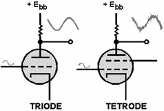
Figure 1-32. - Noise in a tetrode circuit. For these reasons tetrodes are only used in very specialized applications of electronics.
Q30. How does the addition of a screen grid in a tetrode reduce interelectrode capacitance? Q31. What undesirable effect does the screen grid in a tetrode create?
The PENTODE The problem of secondary emission associated with the screen grid of a tetrode has been reduced by - you
guessed it, the addition of another grid. This third grid, called a SUPPRESSOR GRID, is
placed between the screen grid and the plate. The suppressor grid is normally connected either internally or
externally to the cathode and bears the same charge as the cathode. This is shown in figure 1-33. Because of its
negative potential (relative to individual electrons), any electrons that are emitted by the plate, through
secondary emission, are repelled back toward the plate.
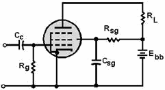
Figure 1-33. - Basic pentode circuit. 1-47
You might think that a grid with a negative potential placed close to the plate would interfere with
the electron stream. However, this is not the case. Because the suppressor grid is negatively charged, it will not
draw grid current. Additionally, the wide spacing within the mesh of the suppressor and its location between two
positive elements of the tube ensures that the suppressor grid's effect on the electron stream will be minimum.
Only the electrons emitted by secondary emission from the plate are affected by the suppressor grid.
Because pentodes do not suffer from secondary emission, they have replaced the tetrode in most applications.
Q32. The suppressor grid is added to a tetrode to reduce what undesirable characteristic of tetrode operation?
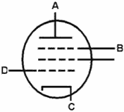
Q33. On the diagram below, name the elements of the vacuum tube and their potentials relative to dc ground.
Summary This chapter has introduced you to the four basic types of vacuum tubes. The following is a summary of
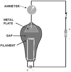
the main points of the chapter. THERMIONIC EMIsSION is caused when metallic substances
are heated to high temperatures. Electrons liberated by thermonic emission provide the conduction currents of
vacuum tubes. A DIODE VACUUM TUBE is composed of two elements: the cathode and the plate.
1-48
The CATHODE is the electron-emitting element of a tube. Cathodes are usually composed
of special materials that are heated either directly or indirectly.
DIODE Operation depends upon current flow through the tube. Because the cathode is the only
electron-emitting element in the tube, current can only flow in one direction, from the cathode to the plate. For
current to flow, the plate must be positive relative to the cathode. When the plate is negative relative to the
cathode, current cannot flow within the tube.
1-49
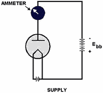
The Characteristic Curve for an electron tube is a graphic plot of plate current (Ip)
versus plate voltage (Ep). From this, dc plate resistance can be computed by the formula:
Factors THAT LIMIT VACUUM TUBE Operation are plate dissipation, maximum average current, maximum
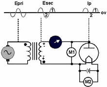
peak-plate current, and peak-inverse voltage. DIODE RECTIFIERS take advantage of the fact
that diodes will conduct in only one direction. When ac voltages are applied to diodes, conduction occurs only on
the alternation that makes the plate positive relative to the cathode. Because of this, the output current
consists of one polarity. Because it flows in pulses rather than continuously, it is called pulsating dc.
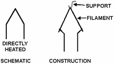
DIODE CONSTRUCTION is the basic construction plan of most vacuum tubes. The tube is
constructed of the following parts: filament and/or cathodes, plates, envelope, and base.
1-50
| - |
Matter, Energy,
and Direct Current |
| - |
Alternating Current and Transformers |
| - |
Circuit Protection, Control, and Measurement |
| - |
Electrical Conductors, Wiring Techniques,
and Schematic Reading |
| - |
Generators and Motors |
| - |
Electronic Emission, Tubes, and Power Supplies |
| - |
Solid-State Devices and Power Supplies |
| - |
Amplifiers |
| - |
Wave-Generation and Wave-Shaping Circuits |
| - |
Wave Propagation, Transmission Lines, and
Antennas |
| - |
Microwave Principles |
| - |
Modulation Principles |
| - |
Introduction to Number Systems and Logic Circuits |
| - |
- Introduction to Microelectronics |
| - |
Principles of Synchros, Servos, and Gyros |
| - |
Introduction to Test Equipment |
| - |
Radio-Frequency Communications Principles |
| - |
Radar Principles |
| - |
The Technician's Handbook, Master Glossary |
| - |
Test Methods and Practices |
| - |
Introduction to Digital Computers |
| - |
Magnetic Recording |
| - |
Introduction to Fiber Optics |
| Note: Navy Electricity and Electronics Training
Series (NEETS) content is U.S. Navy property in the public domain. |
|


