Module 6 - Introduction to Electronic Emission, Tubes, and Power
Supplies
Pages i,
1-1,
1-11,
1-21,
1-31,
1-41,
1-51,
2-1,
2-11,
2-21,
2-31,
3-1,
3-11,
3-21,
3-31,
3-41,
3-51, AI-1, Index
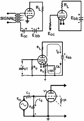
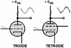
A TRIODE is basically a diode with a control grid mounted between the plate and the cathode.
The control grid gives the triode the ability to amplify signals.
The Operation of a TRIODE depends on the ability of the control grid to either increase
or decrease conduction through the tube in response to an ac input signal. The output voltage is developed across
the tube between the cathode and plate because of the voltage drop across the plate-load resistor changing as the
plate current responds to the input signal. TUBE BIASING is the process of placing a dc
voltage, usually negative, on the grid. Bias has several functions in circuit design. Biasing may be divided into
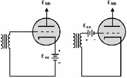
two types: fixed and self. Tubes using fixed bias have a dc voltage applied to their control grids from an
external source such as a battery. Self-
1-51
biasing voltages, on the other hand, are derived from current conducting through the tube. The most
common types of self-biasing are cathode biasing and grid-leak biasing.
The Class of Operation of an Amplifier is determined by the bias applied to a triode.
An amplifier operating as class a conducts continually through the duration of the input cycle. Class AB operation
occurs when the amplifier conducts for more than half but less than the entire duration of the input cycle. a
class B amplifier conducts for only 50% of the input cycle. The class C amplifier conducts for less than half of
the input cycle. TRANSIT TIME is the time required for electrons emitted by the cathode
to reach the plate. Because transit time in a vacuum tube is considerably less than the speed of light, vacuum
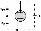
tube operation is affected at high frequencies. Interelectrode Capacitance is created by
the naturally occurring capacitance between elements in a vacuum tube. One effect of interelectrode capacitance is
to feed back a portion of the output
1-52
of a triode to the input. This effect is a prime-limiting factor in applying triodes. It is a major
reason why triodes are seldom used - especially at the higher frequencies.
 MU and TRANSCONDUCTANCE are measures of tube efficiency. Mu (µ), or amplification
factor, is a measure of the amount that plate voltage varies in relation to variation of the input voltage.
Mathematically, mu (µ) is expressed as

TRANSCONDUCTANCE, on the other hand, is a measure of the amount of variation of plate
current caused by a variation of the input signal. Mathematically, it is expressed as:

TETRODES were developed to compensate for the effects of interelectrode capacitance.
Placing a positively charged screen grid between the control grid and plate has the effect of adding a capacitor
in series with the capacitance that exists between the control grid and plate. This reduces total capacitance
below the value of either capacitor as shown by applying the formula:

1-53
 SECONDARY EMIsSION of electrons from the plate is caused by the acceleration of
electrons by the screen grid. This causes the performance of a tetrode to be degraded. In addition to reduced
amplitude, the output signals become noisy. PENTODES do not suffer from the effects of
secondary emission. This is because a negatively charged suppression grid placed between the screen grid and plate
forces any electrons emitted back to the plate. Answers to Questions Q1. Through Q33. A1. By heating it. A2. Because the negatively charged electrons are attracted to the
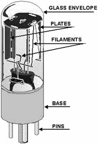
positively charged plate. A3. Filament and plate. A4. Negative. A5. Positive. A6. Pulsating dc. A7. Thoriated-tungsten and oxide-coated metals. A8. They reach
operating temperatures quickly. A9. It serves as a mounting for the tube elements and as the terminal
connection to the circuit. A10. The linear portion. A11. Plate resistant Rp. A12.
Peak Inverse Voltage (PIV). A13. The triode contains a third element called the control rid.
A14. Because it is closer to the cathode. 1-54
A15. a plate load resistor RL A16. To prevent them from drawing grid current.
A17. The input signal A18. +275 volts. A19. a. 100 volts. b. 180º
out of phase. A20. a. Cutoff. b. Saturation. A21. Cathode biasing.
A22. Through the use of a bypass capacitor A23. Rkg, the cathode to grid resistance.
A24. Unequal charge and discharge paths of the coupling capacitor Cc. A25. a. Class B.
b. Class C c. Class A. A26. 42. A27. 340 volts. A28. The
changes in plate current and grid voltage. A29. 240 volts.
A30. The interelectrode capacitance (cpg) is divided between two series capacitances; thus, cpg is greatly
reduced. A31. Secondary emission, and noise. A32. Secondary emission.
1-55
A33. a. Plate, positive. b. Suppressor grid, negative. c.
Cathode, can be negative, positive, or at dc ground potential, depending on biasing type. d. Control
grid, negative.
1-56
| - |
Matter, Energy,
and Direct Current |
| - |
Alternating Current and Transformers |
| - |
Circuit Protection, Control, and Measurement |
| - |
Electrical Conductors, Wiring Techniques,
and Schematic Reading |
| - |
Generators and Motors |
| - |
Electronic Emission, Tubes, and Power Supplies |
| - |
Solid-State Devices and Power Supplies |
| - |
Amplifiers |
| - |
Wave-Generation and Wave-Shaping Circuits |
| - |
Wave Propagation, Transmission Lines, and
Antennas |
| - |
Microwave Principles |
| - |
Modulation Principles |
| - |
Introduction to Number Systems and Logic Circuits |
| - |
- Introduction to Microelectronics |
| - |
Principles of Synchros, Servos, and Gyros |
| - |
Introduction to Test Equipment |
| - |
Radio-Frequency Communications Principles |
| - |
Radar Principles |
| - |
The Technician's Handbook, Master Glossary |
| - |
Test Methods and Practices |
| - |
Introduction to Digital Computers |
| - |
Magnetic Recording |
| - |
Introduction to Fiber Optics |
| Note: Navy Electricity and Electronics Training
Series (NEETS) content is U.S. Navy property in the public domain. |
|


