Module 6 - Introduction to Electronic Emission, Tubes, and Power
Supplies
Pages i,
1-1,
1-11,
1-21,
1-31,
1-41,
1-51,
2-1,
2-11,
2-21,
2-31,
3-1,
3-11,
3-21,
3-31,
3-41,
3-51, AI-1, Index
Chapter 3
Power SUPPLIES Learning Objectives Upon completion of this chapter you will be able to: 1. Identify the various sections of a power
supply.
2. State the purpose of each section of a power supply. 3. Describe the operation of the power
supply from both the whole unit standpoint and from the subunit standpoint. 4. Describe the purpose of the
various types of rectifier circuits used in power supplies. 5. Describe the purpose of the various types
of filter circuits used in power supplies. 6. Describe the operation of the various voltage and current
regulators in a power supply. 7. Trace the flow of ac and dc in a power supply, from the ac input to the
dc output on a schematic diagram. 8. Identify faulty components through visual checks. 9. Identify
problems within specific areas of a power supply by using a logical isolation method of troubleshooting. 10. Apply safety precautions when working with electronic power supplies.
Introduction In the early part of this century when electronics was first introduced, most electronic equipment was powered
by batteries. While the use of batteries allowed the equipment to be portable (to some degree), it also placed
several limitations on how the equipment could be used. Because of their general inefficiency, batteries had to be
either replaced frequently or, if they were rechargeable, kept near a battery charger. Thus, the advantage of
having portable equipment was more than offset by the need to replace or recharge the batteries frequently.
Users of electronic equipment needed a power supply that was reliable, convenient, and cost effective. Since
batteries failed to satisfy these requirements, the "electronic power supply" was developed. In today's Navy,
all electronic equipment, both ashore and on board ship, require some type of power supply. Therefore, this
chapter is of extreme importance to you. We will discuss the sections and individual components of the power
supply and their purposes within the power supply. We will also discuss troubleshooting of each section and its
components.
3-1
The Basic Power SUPPLY Figure 3-1 shows the block diagram of the basic power supply. Most power supplies are made up of four basic
sections: a Transformer, a RECTIFIER, a FILTER, and a
REGULATOR.

Figure 3-1. - Block diagram of a basic power supply. As you can see, the first section is the Transformer. The transformer serves two primary purposes: (1)
to step up or step down the input line voltage to the desired level and (2) to couple this voltage to the
rectifier section. The RECTIFIER section converts the ac signal to a pulsating dc voltage.
However, you will see later in this chapter that the pulsating dc voltage is not desirable. For this reason, a
FILTER
section is used to convert the pulsating dc voltage to filtered dc voltage. The final section, the
REGULATOR, does just what the name implies. It maintains the output of the power supply at a constant
level in spite of large changes in load current or in input line voltage. Depending upon the design of the
equipment, the output of the regulator will maintain a constant dc voltage within certain limits. Now that
you know what each section does, let's trace a signal through the power supply and see what changes are made to
the input signal. In figure 3-2, the input signal of 120 volts ac is applied to the primary of the transformer,
which has a turns ratio of 1:3. We can calculate the output by multiplying the input voltage by the ratio of turns
in the secondary winding to turns in the primary winding. Therefore, the output voltage of our example is: 120
volts ac × 3, or 360 volts ac. Depending on the type of rectifier used (full-wave or half-wave), the output from
the rectifier will be a portion of the input. Figure 3-2 shows the ripple waveform associated with a full-wave
rectifier. The filter section contains a network of resistors, capacitors, or inductors that controls the rise
and fall time of the varying signal so that the signal remains at a more constant dc level. You will see this
more clearly in the discussion of the actual filter circuits. You can see that the output of the filter is at a
180-volt dc level with an ac RIPPLE voltage riding on it. (Ripple voltage is a small ac voltage riding at some dc
voltage level. Normally, ripple voltage is an unwanted ac voltage created by the filter section of a power
supply.) This signal now goes to the regulator where it will be maintained at approximately 180 volts dc to the
load.

Figure 3-2. - Block diagram of a power supply. Q1. What are the four basic sections to a power supply? Q2. What is the purpose of the
regulator?
3-2
The Transformer The transformer has several purposes: In addition to coupling the input ac signal to the power supply, it also
isolates the electronic power supply from the external power source and either steps up or steps down the ac
voltage to the desired level. Additionally, most input transformers have separate step-down windings to supply
filament voltages to both power supply tubes and the tubes in the external equipment (load). Such a transformer is
shown in figure 3-3. Because the input transformer is located in the power supply and is the ultimate source of
power for both the load and the power supply, it is called the Power Transformer. Notice that the
transformer has the ability to deliver both 6.3 and 5 volts ac filament voltages to the electron tubes. The
High-voltage winding is a 1:3 step-up winding and delivers 360 volts ac to the rectifier. This transformer also
has what is called a center tap. This center tap provides the capability of developing two high-voltage outputs
from one transformer.
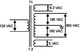
Figure 3-3. - Typical power transformer. Q3. What are the purposes of the transformer in a power supply? Q4. For what are the low
voltage windings in a transformer used? Q5. For what is the center tap on a transformer used?
RECTIFIERS From previous discussions, you know that rectification is the changing
of an ac voltage to a pulsating dc voltage. Now let's discuss the process of rectification. Since a diode
vacuum tube will pass current in only one direction, it is ideally suited for converting alternating current to
direct current. If an ac voltage is applied to a diode, the diode will conduct ONLY DURING The Positive
ALTERNATION of Voltage when the plate of the diode is made positive with respect to the cathode. Figure 3-4 shows a diode connected across the 120-volt ac line. During the positive alternation of the source
voltage, the sine wave applied to the tube makes the plate positive with respect to the cathode. At this time the
diode conducts and plate current flows from the negative supply lead, through the milliammeter, through the tube,
and to the positive supply lead. This is indicated by the shaded area of the output waveform. This current exists
during the entire period of time that the plate is positive with respect to the cathode (for the first 180 degrees
of the input sine wave).
3-3

Figure 3-4. - Simple diode rectifier.
During the negative alternation of plate voltage (dotted polarity signs), the plate is driven negative and the
tube cannot conduct. When conditions prevent the tube from conducting, the tube is said to be in CUTofF.
This is indicated by the dotted waveform. The tube will be in cutoff and no current will flow for the entire
negative alternation. For each 360-degree cycle of input voltage, the tube conducts for 180 degrees and is
in cutoff for 180 degrees. The circuit current therefore has the appearance of a series of positive pulses, as
shown by the shaded areas. Notice that although the current is in the form of pulses, the current always flows
through the circuit in The SAME DirectION. Current that flows in pulses in the same direction is
called
PULSATING DC. The diode has thus RECTIFIED the input voltage. Although the
principle of rectification applies to all rectifier circuits, some rectifiers are more efficient than others. For
this reason, we will explain the three rectifier circuits most commonly used in electronics today-the half-wave,
full-wave, and bridge. A Practical Half-Wave Rectifier Figure 3-5 is a diagram of
a complete half-wave rectifier circuit. For the diode to be used as a rectifier, it must be connected in series
with a load device (RL
for this circuit), through which the direct current flows. Because Navy electronic equipment requires various
input voltages, it is necessary to have a rectified voltage that is greater (or smaller in some cases) than the
source voltage. The rectifier plate circuit is supplied power from a step-up (or step-down) transformer. Notice
that the transformer has the two secondary windings mentioned earlier. The lower winding supplies high voltage to
the plate and cathode of the diode, and the upper winding supplies a low ac voltage to the filaments of the diode.
Notice also that the cathode of the diode is connected to the secondary winding of the transformer through the
load resistor (RL). Any current flowing through the tube also flows through the load resistor, causing
a voltage to be developed across it. The magnitude of the voltage developed across the load resistor is directly
proportional to the amount of current flowing through it (Ohm's law: E = IR). 3-4
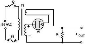
Figure 3-5. - Half-wave rectifier circuit.
You will better understand the operation of the half-wave rectifier circuit if it is redrawn in the form of a
simplified series circuit. As you can see in figure 3-6, the diode (V1) and load resistor (RL) are in
series with the secondary winding of the transformer. During the positive alternation of the input, as the voltage
in the secondary winding increases, the current through diode (V1) and load resistor (RL) increases.
Since the diode tube and the load resistor form a series circuit, the same current flows through both the tube and
the resistor. This current produces a voltage drop across the tube and the load resistor, which have polarities as
shown. Since the plate resistance of the tube is only about 500 ohms and the resistance of the load resistor is
10,000 ohms, approximately 95 percent of the applied 425 volts is dropped across the load resistor (425 × .95 =
404 V) and 5 percent (425 × .05 = 21 V) across the tube.
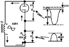
Figure 3-6. - Simplified half-wave rectifier circuit and waveforms. During the negative half of the alternation of input voltage, the tube cannot conduct and no current
flows in the circuit. Since there is no current flow through RL, the load voltage remains at zero volts throughout
the negative alternation. During this time the entire negative alternation is felt across the tube. The reason for
this is derived from Kirchhoff's law, which states:
EL + Eb = Ea
The sum of the load voltage and diode voltage equals the applied voltage.
3-5
Since a half-wave rectifier conducts once for each full cycle of input voltage, the frequency of the
pulses is the same as the frequency of the input sine wave. The output pulse frequency is called RIPPLE
Frequency. If the rectifier circuit is supplied power from a 60-hertz ac line voltage, 60 pulses of load
current will occur each second. Therefore, The RIPPLE Frequency of a Half-WAVE RECTIFIER Is The SAME AS
The LINE Frequency.
If a series of current pulses like those obtained from a half-wave rectifier is applied to a load
resistance, an average amount of power will be dissipated over a given period of time. This average dc power is
determined by the amplitude of the pulses and the time delay between pulses. The higher the peak amplitude of the
pulses or the less the time between pulses, the greater the average dc power supplied to the load. To determine
average dc voltage (Eavg), it is necessary to know the average value of the pulses and the peak value
of load voltage. This is illustrated in figure 3-7.
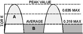
Figure 3-7. - Peak and average values for a half-wave rectifier. Since current and voltage waveforms in a half-wave rectifier circuit are essentially half sine waves, we
can develop a conversion factor. The formula for average value was discussed earlier in NEETS, module 2. By now
you should know that the average value for a full sine wave is .637 times its peak or maximum value. Therefore, if
you want the average value of a half-wave rectifier output, you should multiply half the value of .637 (.318)
times the peak or maximum voltage, as expressed in the following equation:
Eavg (the average load voltage) = .318 × Emax
Where:
Emax = The peak value of the load voltage pulse
In most applications the drop across the rectifier tube is small compared to the load voltage, so we can
assume Emax in our equation to be the same as the peak value of the input sine wave. Since the load current
has the same wave shape as the load voltage, we can modify the equation so that it applies to the load current.
Thus,
Iavg (the average load current) = .318 × Imax
Where:
Imax = The peak load current
If a line is drawn through the rectified waveform at a point that is 0.318 of the distance from zero to
maximum, the waveform will be divided so that area a is equal to area B (fig. 3-7). Therefore, current or 3-6
voltage pulses with a value of .318 of the peak value have the same effect on the load as a steady
voltage or current. The half-wave rectifier uses the transformer during only one-half of the cycle.
Therefore, for any given size transformer, less power is developed than if the
transformer were used on both halves of the cycle. In other words, to obtain large amounts of power, the half-wave
transformer must be relatively large in comparison to what it would have to be if both
halves of the cycle were used. This disadvantage limits the use of the half-wave rectifier to applications
that require a very small current drain. The half- wave rectifier is widely used for commercial ac and dc radio
receivers and other applications where inexpensive voltage supplies will suffice. As you can see from your study
on half-wave rectifiers, this type of circuit placed many limitations on electronic equipment. For this reason
another type of rectifier circuit had to be developed. One of the factors that had to be considered was how to use
the full output from the transformer to obtain the highest average voltage and current. Thus, the
FULL-WAVE rectifier was developed. Q6. Does a rectifier tube conduct on the positive or negative
alternation of the input signal? Q7. What term is used to describe the period when the diode is not
conducting? Q8. Current that flows in pulses in the same direction is called ______. Q9. For a
diode to act as a rectifier, should it be connected in series or parallel with the load? Q10. What is
the Ripple frequency of a half-wave rectifier if the input frequency is 60 Hz? Q11. What is the equation
for determining average voltage in a half-wave rectifier?
The Conventional Full-Wave Rectifier A full-wave rectifier is a device that
has two or more diodes arranged so the load current flows in the same direction during each half cycle of the ac
supply. A schematic diagram of a simple full-wave rectifier is shown in figure 3-8. The transformer
supplies the source voltage for two rectifier tubes (V1 and V2). This power transformer has a
CENTER-TAPPED
high-voltage secondary winding that is divided into two equal parts (W1 and W2). W1 provides the source voltage
for V1 and the other winding (W2) provides the source voltage for V2. The connections to the diodes are arranged
so that the diodes conduct on alternate half cycles.
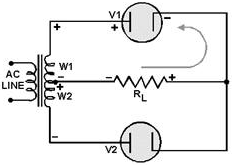
Figure 3-8. - Simple full-wave rectifier (first alternation). 3-7
During one alternation of the secondary voltage, the polarities will be as shown in figure 3-8. The
source for diode V2 is the voltage induced into the lower half of the transformer secondary winding (W2). At the
specific instant of time shown in the figure, the plate voltage on V2 is negative, and V2 cannot conduct. Throughout the period of time during which the plate of V2 is negative, the plate of V1 is positive. This is
illustrated by the polarity signs across W1, which indicate the source for V1. Since the plate of V1 is positive,
it conducts, causing current to flow through the load resistor in the direction shown by the arrow. Figure
3-9 shows the next half cycle of secondary voltage. As you can see, the polarities across W1 and W2 are reversed.
During this alternation the plate of V1 is driven negative and V1 cannot conduct.
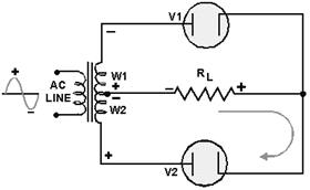
Figure 3-9. - Simple full-wave recliner (second alternation). For the period of time that V1 is negative, the plate of V2 is positive, permitting V2 to conduct.
Notice that the plate current of V2 passes through the load resistor in the same direction as did the plate
current of V1. In this circuit arrangement, a pulse of load current flows during each alternation of the input
cycle. Since both alternations of the input voltage cycle are used, the circuit is called a FULL-WAVE
RECTIFIER.
Now that you have a basic understanding of how a full-wave rectifier works, let's cover in detail a
practical full-wave rectifier and its waveforms. A Practical Full-Wave Rectifier A practical full-wave rectifier circuit is shown in figure 3-10. It uses two diodes (V1 and V2) and a
center-tapped transformer (T1). When the center tap is grounded, the voltages at the opposite ends of the
secondary windings are 180 degrees out of phase with each other. Thus, when the voltage at point a is positive
with respect to ground, the voltage at point B is negative with respect to ground. Let's examine the operation of
the circuit during one complete cycle.
3-8

Figure 3-10. - Complete full-wave rectifier.
During the first half-cycle (as indicated by solid arrows) the plate of V1 is positive with respect to ground
and the plate of V2 is negative. As shown, current flows from ground (center tap), up through the load resistor
(RL), through diode V1 to point A. In the transformer, current flows from point A, through the upper winding and
back to ground (center tap). When V1 conducts, it acts like a closed switch so that the positive half-cycle is
felt across the load. During the second half-cycle (broken lines), the polarity of the applied voltage has
reversed Now the plate of V2 is positive with respect to ground and the plate of V1 is negative. Only V2 can
conduct. Current now flows, as shown, from ground (center tap), up through the load resistor (R L), through diode
V2 to point B of T1. In the transformer, current flows from point B up through the lower windings and back to
ground (center tap). Notice that the current flows across the load resistor (R L) in the SAME DirectION
for both halves of the input cycles. The output waveform from the full-wave rectifier consists of two
pulses of current (or voltage) for each cycle of input voltage. The ripple frequency at the output of the
full-wave rectifier is therefore
TWICE The LINE Frequency. The higher ripple frequency at the output of a full-wave
rectifier has a distinct advantage: Because of the higher pulse frequency, the output is closely approximate to
pure dc. This higher frequency also makes filtering much easier than the output of the half-wave rectifier. In terms of peak value, the average value of current and voltage at the output of the full-wave rectifier is twice
as great as the average current or voltage at the output of the half-wave rectifier. The relationship between peak
and average values is illustrated in figure 3-11.
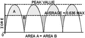
Figure 3-11. - Peak and average values for a full-wave rectifier. 3-9
Since the output waveform is essentially a sine wave with both alternations at the same polarity, the
average current or voltage is 63.7 percent (or .637) of the peak current or voltage. As an equation:
Eavg (the average load voltage) = .637 × Emax Where Emax
= The peak value of the load voltage pulse And Iavg (the average load current) = .637 ×
Imax Where: Imax = The peak value of the load current pulse
Example: The total voltage across the high-voltage secondary of a transformer used to supply a full- wave
rectifier is 600 volts. Find the average load voltage. (Ignore the drop across the rectifier tube.) Solution: Since the total secondary voltage is 600 volts, each diode is supplied one-half of this value, or 300
volts. As the secondary voltage is an rms value, the peak load voltage is: Emax = 1.414 × Es
Emax = 1.414 × 300 Emax = 424 volts The average load voltage is:
Eavg = .637 × Emax Eavg = .637 × 424
Eavg = 270 volts Note: If you have problems with this equation, review NEETS, module 2,
pertaining to this area. As you may recall from your past studies in electricity, there are advantages and
disadvantages in every circuit. The full-wave rectifier is no exception. In studying the full-wave rectifier, you
have found that when the output frequency is doubled, the average voltage is also doubled, and the resulting
signal is much easier to filter because of the high-ripple frequency. The only disadvantage is that the peak
voltage in a full-wave rectifier is only half the peak voltage in a half-wave rectifier. This is because the
secondary of the power transformer in a full-wave rectifier is center tapped; therefore only half the source
voltage goes to each diode. Fortunately, there is a rectifier that produces the same peak voltage as a
half-wave rectifier and the same ripple frequency as a full-wave rectifier. This circuit, called the
BRIDGE RECTIFIER, will be the chapter of our next discussion. Q12. What is the ripple frequency
of a full-wave rectifier with an input frequency of 60 Hz?
3-10
| - |
Matter, Energy,
and Direct Current |
| - |
Alternating Current and Transformers |
| - |
Circuit Protection, Control, and Measurement |
| - |
Electrical Conductors, Wiring Techniques,
and Schematic Reading |
| - |
Generators and Motors |
| - |
Electronic Emission, Tubes, and Power Supplies |
| - |
Solid-State Devices and Power Supplies |
| - |
Amplifiers |
| - |
Wave-Generation and Wave-Shaping Circuits |
| - |
Wave Propagation, Transmission Lines, and
Antennas |
| - |
Microwave Principles |
| - |
Modulation Principles |
| - |
Introduction to Number Systems and Logic Circuits |
| - |
- Introduction to Microelectronics |
| - |
Principles of Synchros, Servos, and Gyros |
| - |
Introduction to Test Equipment |
| - |
Radio-Frequency Communications Principles |
| - |
Radar Principles |
| - |
The Technician's Handbook, Master Glossary |
| - |
Test Methods and Practices |
| - |
Introduction to Digital Computers |
| - |
Magnetic Recording |
| - |
Introduction to Fiber Optics |
| Note: Navy Electricity and Electronics Training
Series (NEETS) content is U.S. Navy property in the public domain. |
|


