Module 6 - Introduction to Electronic Emission, Tubes, and Power
Supplies
Pages i,
1-1,
1-11,
1-21,
1-31,
1-41,
1-51,
2-1,
2-11,
2-21,
2-31,
3-1,
3-11,
3-21,
3-31,
3-41,
3-51, AI-1, Index
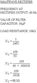
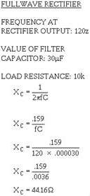
As you can see from the calculations, when the output frequency of the rectifier is doubled, the
impedance of the capacitor is reduced by one-half. Therefore, when the simple capacitor filter is used in 3-21
conjunction with a full-wave or bridge rectifier, improved filtering is provided because the increased
ripple frequency decreases the capacitive reactance of the filter capacitor. This allows the ac component to be
passed through the capacitor more easily. Therefore, the output of a full-wave rectifier is much easier to filter
than that of a half-wave rectifier. It should be obvious that the smaller the XC of the filter capacitor
in respect to the load resistance, the better the filtering action. By using the largest possible capacitor, we
achieve the best filtering. The load resistance is also an important consideration. If load resistance is made
small, the load current increases, and the average value of output voltage (Eavg) decreases. The RC
discharge time constant is a direct function of the value of the load resistance; therefore, the rate of capacitor
voltage discharge is a direct function of the current through the load. The greater the load current, the more
rapid the discharge of the capacitor, and the lower the average value of output voltage. For this reason, the
simple capacitor filter is seldom used with rectifier circuits that must supply a relatively large load current.
Q17. What is the most basic type of filter? Q18. In a capacitor filter, is the capacitor in
series or parallel with the load? Q19. Is better filtering achieved at a high frequency or at a low
frequency at the input of the filter? Q20. Does a filter circuit increase or decrease the average output
voltage? Q21. What determines the rate of discharge of the capacitor in a filter circuit?
Q22. Does low ripple voltage indicate good or bad filtering? Q23. Is a full-wave rectifier output
easier to filter than that of a half-wave rectifier? In general, with the supply voltage removed from the
input to the filter circuit, one terminal of the filter capacitor can be disconnected from the circuit.
Caution
REMEMBER-AN UNDIsCHARGED Capacitor RETAINS ITS POLARITY and HOLDS ITS CHARGE for Long
PERIODS of TIME. to BE SAFE, use a PROPER Safety ShortING PROBE to DIsCHARGE The Capacitor to BE TESTED WITH The
Power ofF BEforE CONNECTING Test Equipment OR DIsCONNECTING The Capacitor. You can check the capacitor by using a capacitance analyzer to determine its effective capacitance and
leakage resistance. During these checks it is very important that you observe correct polarity if the capacitor is
an electrolytic. a decrease in capacitance or losses within the capacitor can cause the output to be below normal
and also cause excessive ripple amplitude. If a suitable capacitance analyzer is not available, you can
get an indication of leakage resistance by using an ohmmeter. You can make resistance measurements across the
terminals of the capacitor to determine whether it is shorted, leaky, or open. When you test electrolytic
capacitors, set the ohmmeter to the high range, and connect the test probes across the capacitor. Be careful to
observe polarity. This is important because current flows through an electrolytic capacitor with less opposition
in one direction than in the other. If you do not observe the correct polarity, you will get an incorrect reading
and you may damage the meter. When you first connect the test probes, a large deflection of the meter should take
place, and then the pointer should return slowly toward the infinite-ohms position as the capacitor charges. For
a good capacitor with a rated working voltage of 450 volts dc, the final reading on the
3-22
ohmmeter should be over 500,000 ohms. (A rough rule of thumb for high-voltage capacitors is at least
1000 ohms per volt.) Low-voltage electrolytic capacitors (below 100 volts rating) should indicate approximately
100,000 ohms. If the ohmmeter does not deflect when you make the resistance check explained above, you
have found an open-circuit capacitor. A steady full-scale deflection of the pointer at zero ohms
indicates that the capacitor being tested is shorted. An indication of a leaky capacitor is a steady
reading on the scale somewhere between zero and the minimum acceptable value. (Be certain this reading is not
caused by an in-circuit shunting part.) To be valid, these capacitor checks should be made with the capacitor
completely disconnected from the circuit in which it operates. In high-voltage filter capacitor
applications, paper and oil-filled capacitors are used in addition to mica and ceramic capacitors (for
low-capacitance values). In this case, polarity is of no importance unless the capacitor terminals are marked plus
or minus. It is, however, good maintenance practice to use the output polarity of the circuit as a guide,
connecting positive to positive, and negative to negative. Thus, any adverse effects of polarity on circuit tests
are minimized and the possibility of damage to components or to test equipment is eliminated. The
LC Choke-Input Filter The LC choke-input filter is used primarily in power supplies where good
voltage regulation is important and where the output current is relatively high and subject to varying load
conditions. This filter is used in high-power applications such as those found in radar and communication
transmitter power supplies. In figure 3-26 you can see that this filter consists of an input inductor or
filter-choke (L1) and an output filter capacitor (C1).
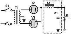
Figure 3-26. - Full-wave rectifier LC choke-input filter. Inductor L1 is placed at the input to the filter and is in series with the output of the rectifier
circuit. Since the action of an inductor is to oppose any change in current flow, the inductor tends to keep a
constant current flowing to the load throughout the complete cycle of the applied voltage. As a result, the output
voltage never reaches the peak value of the applied voltage; instead, the output voltage approximates the average
value of the rectified input to the filter, as shown in figure 3-27.
3-23
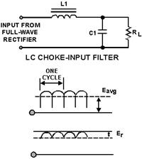
Figure 3-27. - Waveforms for a LC choke-input filter. The reactance of the inductor (XL) reduces the amplitude of ripple voltage without reducing
the dc output voltage by an appreciable amount. (The dc resistance of the inductor is just a few ohms.)
The shunt capacitor (C1) charges and discharges at the ripple frequency rate, but the amplitude of the ripple
voltage (Er) is relatively small because the inductor (L1) tends to keep a constant current flowing
from the rectifier circuit to the load. In addition, the reactance of the shunt capacitor (XC) presents
a low impedance to the ripple component existing at the output of the filter, and thus shunts the ripple component
around the load. The capacitor attempts to hold the output voltage relatively constant at the average value of the
voltage.
The value of the filter capacitor (C1) must be relatively large to present a low opposition (XC) to the
pulsating current and to store a substantial charge. The rate of the charge for the capacitor is limited by the
low impedance of the ac source (transformer), the small resistance of the diode, and the counter emf developed by
the coil. Therefore, the RC charge time constant (fig. 3-28) is short compared to its discharge time.
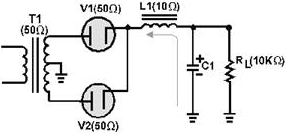
Figure 3-28. - LC choke-input filter (circuit resistance). 3-24
As a result, when the pulsating voltage is first applied to the LC choke-input filter, the inductor or
filter choke (L1) produces a counter emf that opposes the constantly increasing input voltage. The net result is
to effectively prevent the rapid charging of the filter capacitor (C1). Thus, instead of reaching the peak value
of the input voltage, C1 only charges to the average value of the input voltage. After the input voltage reaches
its peak and decreases sufficiently, the capacitor (C1) attempts to discharge through the load resistance (RL).
C1 will attempt to discharge as indicated in figure 3-29. Because of its relatively long discharge time
constant, C1 can only partially discharge.
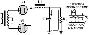
Figure 3-29. - LC choke-input filter (discharge path). The larger the value of the filter capacitor, the better the filtering action. However, due to the
physical size, there is a practical limitation to the maximum value of the capacitor. The inductor or
filter choke (L1) maintains the current flow to the filter output (capacitor C1 and load resistance RL)
at a nearly constant level during the charge and discharge periods of the filter capacitor. The series
inductor (L1) and the capacitor (C1) form a voltage divider for the ac component (ripple) of the applied input
voltage. This is shown in figure 3-30. As far as the ripple component is concerned, the inductor offers a high
impedance (Z) and the capacitor offers a low impedance. As a result, the ripple component (Er)
appearing across the load resistance is greatly attenuated (reduced). Since the inductance of the filter choke
opposes changes in the value of the current flowing through it, the average value of the voltage produced across
the capacitor contains a much smaller value of ripple component (Er), as compared with the value of
ripple produced across the coil.
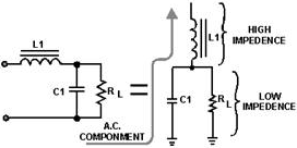
Figure 3-30. - LC choke-input filter (as voltage divider).
3-25
Now look at figure 3-31, which illustrates a complete cycle of operation where a full-wave rectifier
circuit is used to supply the input voltage to the filter. The rectifier voltage is developed across capacitor C1.
The ripple voltage in the output of the filter is the alternating component of the input voltage reduced in
amplitude by the filter section.
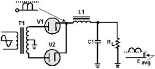
Figure 3-31. - Filtering action of an LC choke-input filter. Each time the plate of a diode goes positive with respect to the cathode, the diode conducts and C1
charges. Conduction occurs twice during each cycle for a full-wave rectifier. For a 60-hertz supply, this produces
a ripple frequency of 120 hertz. Although the diodes alternate (one conducts while the other is nonconducting),
the filter input voltage is not steady. As the plate voltage of the conducting diode increases (on the positive
half of the cycle), capacitor C1 charges-the charge being limited by the impedance of the secondary transformer
winding, the diode's forward (cathode-to-plate) resistance, and the counter emf developed by the choke. During the
nonconducting interval, (when the plate voltage drops below the capacitor charge voltage), C1 discharges through
the load resistance RL. The components in the discharge path cause a long time constant; thus C1 discharges slower
than it charges.
The choke (L1) is usually of a large value, on the order of 1 to 20 henries, and offers a large inductive
reactance to the 120-hertz ripple component produced by the rectifier. Therefore, the effect that L1 has on the
charging of the capacitor (C1) must be considered. Since L1 is connected in series with the parallel branch
consisting of C1 and RL, a division of the ripple ac voltage and the output dc voltage occurs. The greater the
impedance of the choke, the less the ripple voltage that appears across C1 and the output. The dc output voltage
is fixed mainly by the dc resistance of the choke. Now that you have read how the LC choke-input filter
functions, let's take a look at it using actual component values. For simplicity, the input frequency at the
primary of the transformer will be 117 volts 60 hertz. We will use both half-wave and full-wave rectifier circuits
to provide the input to the filter. Starting with the half-wave configuration as shown in figure 3-32,
the basic parameters are: with 117 volts ac rms applied to the T1 primary, 165 volts ac peak-to-peak is available
at the secondary [(117 V) × (1.414) = 165 V]. You should recall that the ripple frequency of this half-wave
rectifier is 60 hertz. Therefore, the capacitive reactance of C1 is:
3-26
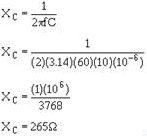
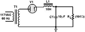
Figure 3-32. - Half-wave rectifier with an LC choke-input filter. This means that the capacitor (C1) offers 265 ohms of opposition to the ripple current. Note, however,
that the capacitor offers an infinite impedance to direct current. The inductive reactance of L1 is:
XL = 2!fL
XL = (2) (3.14) (60) (10)
XL = 3.8 Kilohms This shows that L1 offers a relatively high opposition (3.8 kilohms) to the ripple in comparison to the
opposition offered by C1 (265 ohms). Thus, more ripple voltage will be dropped across L1 than across C1. In
addition, the impedance of C1 (265 ohms) is relatively low in respect to the resistance of the load (10
kilohms). Therefore, more ripple current flows through C1 than the load. In other words, C1 shunts most of the ac
component around the load. Let's go a step further and redraw the filter circuit so that you can see the
voltage divider action. (Refer to figure 3-33.) Remember, the 165 volts peak-to-peak 60 hertz provided by the
rectifier consist of both an ac and a dc component. The first discussion will be about the ac component. Looking
at figure 3-33, you see that the capacitor (C1) offers the least opposition (265 ohms) to the ac component;
therefore, the greatest amount of ac will flow through C1. (The heavy line indicates current flow through the
capacitor.) Thus the capacitor bypasses, or shunts, most of the ac around the load. By combining the XC
of C1 and the resistance of RL into an equivalent circuit, you will have an equivalent impedance of 265
ohms.
3-27

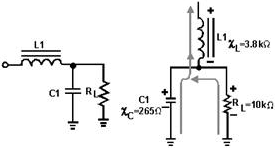
Figure 3-33. - AC component in an LC choke-input filter. You now have a voltage divider as illustrated in figure 3-34. You should see that because of the
impedance ratios, a large amount of ripple voltage is dropped across L1, and a substantially smaller amount is
dropped across C1 and RL. You can further increase the ripple voltage across L1 by increasing the inductance:
XL = 2!fL
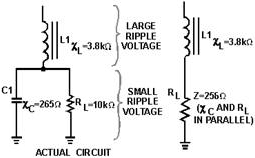
Figure 3-34. - Actual and equivalent circuits. Now let's discuss the dc component of the applied voltage. Remember, a capacitor offers an infinite (")
impedance to the flow of direct current. The dc component, therefore, must flow through RL and L1. As far as the
dc is concerned, the capacitor does not exist. The coil and the load are, therefore, in series with each other.
The dc resistance of a filter choke is very low (50 ohms average). Therefore, most of the dc component is
developed across the load and a very small amount of the dc voltage is dropped across the coil, as shown in figure
3-35.
3-28
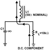
Figure 3-35. - DC component in an LC choke-input filter. As you may have noticed, both the ac and the dc components flow through L1, and because the coil is
frequency sensitive, it provides a large resistance to ac and a small resistance to dc. In other words, the coil
opposes any change in current. This property makes the coil a highly desirable filter component. Note that the
filtering action of the LC capacitor input filter is improved when the filter is used in conjunction with a
full-wave rectifier as shown in figure 3-36. This is due to the decrease in the XC of the filter
capacitor and the increase in the XL of the choke. Remember, the ripple frequency of a full-wave rectifier is
twice that of a half-wave rectifier. For a 60-hertz input, the ripple will be 120 Hertz. Let's briefly calculate
the XC of C1 and the XL
of L1:
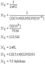
3-29
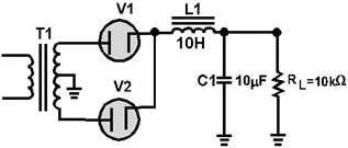
Figure 3-36. - Full-wave rectifier with an LC choke-input filter. It should be apparent that when the XC of a filter capacitor is decreased, it provides less opposition
to the flow of ac. The greater the ac flow through the capacitor, the lower the flow through the load. Conversely,
the larger the XL of the choke, the greater the amount of ac ripple developed across the choke; consequently, less
ripple is developed across the load. This condition provides better filtering. Q24. In an LC
choke-input filter, what prevents the rapid charging of the capacitor? Q25. What is the value usually
chosen for a filter choke? Q26. If the inductance of a choke-input filter is increased, will the output
ripple voltage amplitude (Er)increase or decrease? An LC choke-input filter is subject to
several problems that can cause it to fail. The filter capacitors are subject to open circuits, short circuits,
and excessive leakage. The series inductor is subject to open windings and, occasionally, shorted turns or a short
circuit to the core. The filter capacitor in the choke-input filter circuit is not subject to extreme
voltage surges because of the protection offered by the inductor; however, the capacitor can become open, leaky,
or shorted. Shorted turns in the choke may reduce the value of inductance below the critical value. This
will result in excessive peak-rectifier current, accompanied by an abnormally high output voltage, excessive
ripple amplitude, and poor voltage regulation. a choke winding that is open, or a choke winding that is shorted to
the core will result in a no-output condition. a choke winding that is shorted to the core may cause overheating
of the rectifier element(s), blown fuses, and so forth. To check the capacitor, first remove the supply
voltage from the input to the filter circuit. Then disconnect one terminal of the capacitor from the circuit.
Check the capacitor with a capacitance analyzer to determine its capacitance and leakage resistance. When the
capacitor is electrolytic, be sure to use the correct polarity at all times. a decrease in capacitance or losses
within the capacitor can decrease the efficiency of the filter and produce excessive ripple amplitude. If a
suitable capacitance analyzer is not available, you can use an ohmmeter to check for leakage resistance. The test
procedure is the same as that described for the input capacitor filter. So far, this section has
discussed in detail the operation and troubleshooting of the basic inductive and capacitive filter circuits. For
the two remaining types of filters, we will discuss only the differences between them and the other basic filters.
3-30
| - |
Matter, Energy,
and Direct Current |
| - |
Alternating Current and Transformers |
| - |
Circuit Protection, Control, and Measurement |
| - |
Electrical Conductors, Wiring Techniques,
and Schematic Reading |
| - |
Generators and Motors |
| - |
Electronic Emission, Tubes, and Power Supplies |
| - |
Solid-State Devices and Power Supplies |
| - |
Amplifiers |
| - |
Wave-Generation and Wave-Shaping Circuits |
| - |
Wave Propagation, Transmission Lines, and
Antennas |
| - |
Microwave Principles |
| - |
Modulation Principles |
| - |
Introduction to Number Systems and Logic Circuits |
| - |
- Introduction to Microelectronics |
| - |
Principles of Synchros, Servos, and Gyros |
| - |
Introduction to Test Equipment |
| - |
Radio-Frequency Communications Principles |
| - |
Radar Principles |
| - |
The Technician's Handbook, Master Glossary |
| - |
Test Methods and Practices |
| - |
Introduction to Digital Computers |
| - |
Magnetic Recording |
| - |
Introduction to Fiber Optics |
| Note: Navy Electricity and Electronics Training
Series (NEETS) content is U.S. Navy property in the public domain. |
|


