|
August 1962 Electronics World
 Table of Contents
Wax nostalgic about and learn from the history of early electronics. See articles
from
Electronics World, published May 1959
- December 1971. All copyrights hereby acknowledged.
|
The header image accompanying
John Frye's "Mac's Service Shop"
technodramas™ underwent half a dozen or so versions
throughout its multi-decade run. It is the first I recall seeing this particular
version. The title of the series also evolved over time to
reflect the era. It began as "Mac's Radio Service Shop" in the 1940s, then changed
to just "Mac's Service Shop" as TVs entered the scene more prominently in the 1950s.
From there is went to "Mac's Electronic Service" in the 1960s, as evidenced by this
1962 edition. Then by the 1970s it was back to "Mac's Service Shop." The names of
the magazines in which it appeared changed over that time period as well. See the
complete list of episodes at the bottom of this page.
This August 1962 installment of "Mac's Electronics Service" entitled
"Openers, Anyone?" discussed remote garage door openers that were getting
popular in the day. As usual there is a valuable lesson taught in the story, but
what really stands out in this case is how the diodes in the schematic have a "+"
sign shown on the cathode. Surely it was a printer's mistake since even though that
was the era when great debates were taking place over whether electrical current
flowed from positive to negative or vice-versa, there was no argument over whether
the more negative voltage needed to be connected to the cathode (vacuum tube or
semiconductor) in order for current to flow.
Mac's Electronics Service: Openers, Anyone?
 By John T. Frye
"Sure took you long enough to clean that tuner," Mac commented acidly to Barney,
his assistant, as the latter came into the service department. "Was the customer
a good-looking girl?"
"No; matter of fact, she was an elderly widow," Barney retorted, parking his
tube caddy on the side bench. "It didn't take me long to clean the tuner and reset
the channels. but then the customer asked if I would look at her radio-controlled
garage door opener that had gone on the fritz. Her late husband had bought the thing
in kit form and had installed it himself. She could still operate the door with
the push-button on the wall of the garage. but punching the button on the dashboard
of her car had no effect whatever. She said the thing had worked perfectly until
just this last week. Fortunately she is a methodical woman and had saved the instruction
manuals that came with the transmitter and receiver; so I said I'd take a look at
it.
"First I checked out the transmitter in the car. This was easy. Following instructions
in the manual, I simply pulled out the antenna plug and stuck in a little dummy
antenna consisting of a #47 pilot lamp fastened to an RCA phono plug. When I pushed
the dash button, the bulb lighted to normal brilliance; so I figured the transmitter
was okay.
"Next I took the case off the receiver unit fastened on the framework of the
door-opening mechanism next to the motor. A 6BH6 was stone cold; so I put in a new
one. That took care of the trouble. The transmitter opened and closed the door perfectly.
But by now I was interested in the circuits; so I took a few minutes more to look
over the diagrams of the transmitter and receiver and figure out how they work.
Remember now: you're always telling me I should satisfy my curiosity about any electronic
device, no matter if I expect to service it or not."
"Okay; so I talk too much," Mac grunted; but he grinned in spite of himself.
"The transmitter uses one-half a 6AU8 as a crystal oscillator and the other half
as a power amplifier - or 'final,' as we hams call it. A 12BH7 with its plates,
grids, and cathodes strapped together functions as a power audio oscillator whose
output modulates the final r.f. amplifier. By connecting different amounts of available
fixed capacitance across the audio oscillator coil, anyone of three different modulating
frequencies can be had. A non-synchronous vibrator and transformer convert the 12-volt
d.c. battery voltage into a stepped-up a.c. voltage that is rectified by two silicon
rectifiers in a voltage doubling circuit to produce 220 volts for the plates of
the tubes. The filaments are connected between ground and the ignition switch so
they light whenever the switch is on. The dash push-button activates the vibrator
to produce output from the transmitter.
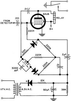
The portion of the opener receiver Mac visualized on his "mental
blackboard."
"The receiver, though, is more interesting. Input from a quarter-wave antenna
fastened beneath the car goes to an antenna transformer whose slug-tuned secondary
feeds the grid of a 6BH6. Another transformer, this time with its tuned primary
in the plate circuit of the 6BH6, feeds a crystal diode with the secondary. The
d.c. voltage developed by the rectification of the carrier by this diode is used
on the grid of the tube as a.g.c, voltage to keep the detector output relatively
equal over a wide range of input signal strength. Audio recovered by the detector
action is fed through a coupling capacitor to the grid of a 6AU6. A 5000-ohm relay
coil is in the plate circuit of this tube, but there is little current through the
coil normally because the grid of the tube is biased to cut-off with voltage developed
by rectifying arid filtering the 6-volt filament supply. Incidentally, this high
bias keeps the tube from amplifying the audio on its grid by any appreciable amount.
"Now we come to the tricky part; so get out that mental blackboard of yours and
let's see how good you are at following a word description of a circuit. Imagine
the familiar diamond shape of a bridge circuit. The two right-hand legs are 220k
resistors. Starting at the left corner and going up to the right, we see a 22k resistor
and then a silicon diode with the plus terminal to the right. Starting at the same
point and going down and to the right, we see a tapped variable inductance audio
choke tuned with a 3000-μμf. capacitor, and the tap goes through a 220k-ohm
resistor across the bridge to the junction of the other two 220k resistors. On beyond
this notch filter - for that's what the resistor-choke-capacitor combination really
is - there's another silicon diode with its plus terminal also to the right. Okay
so far?"
"Drive on."
"Well imagine a 2-μf. capacitor connected from top to bottom of our bridge, with
the positive terminal at the top. Next picture a 0.01 capacitor connected from the
right-hand corner to the bottom corner. Finally, in your mind's eye, connect the
top of the bridge through a 220k resistor to the grid of the 6AU6, the bottom of
it to our bias voltage developed by rectifying the filament voltage, and the left-hand
corner through an 0.01 capacitor to the plate of the 6AU6. See how it works?"
"Oh I think so," Mac said with a faint smile. "The bias for the 6AU6 is fed to
the grid of the tube through the resistive right-hand half of the bridge and suffers
no alteration as long as no audio signal is delivered to the bridge from the plate
of the 6AU6. Even when such a signal is delivered, as long as the frequency is far
removed from the sharp resonant frequency of the notch filter, this bias voltage
is not affected. This is because the notch filter presents very little impedance
to the non-resonant signal - no more than that of the 22k resistor in the other
leg of the bridge - so the signal is presented equally to the two silicon diodes
and produces two equal bucking voltages across their respective load resistors in
the right-hand side of the bridge. These two equal and opposing voltages cancel
each other, and there is no effect on the bias of the 6AU6.
"However, when the audio signal is of the frequency to which the notch filter
is tuned, this filter presents a very high impedance to the signal and practically
none of it reaches the diode in that leg of the bridge. The signal passes as before
through the 22k resistor in the other leg, though and the rectifier in this leg
produces a positive voltage across the 2-μf. capacitor that opposes the negative
bias voltage flowing through the bridge. The bias on the 6AU6 goes down and the
tube amplification goes up so that more signal is delivered to the unbalanced bridge,
resulting in still more unbalance and more plate current through the 6AU6. This
action continues to build up until the tube reaches a condition of saturated plate
current and the relay contacts are closed, operating the door's opening and closing
mechanism. That 2-μf. capacitor requires an appreciable length of time to charge,
and this prevents short-duration transients from tripping the mechanism."
"Well, I'll be - I" Barney marveled.
"It took me a long time to figure out that circuit, even with the description
right in front of me; yet you reeled it off as though you were reading over my shoulder."
"I gotta confess," Mac said with a chuckle. "I did read the book. When you said
that garage door opener came in a kit form, I suspected it might be the Heathkit
job, and I had read up on that circuit not more than a month ago. I, too, was rather
intrigued by the clever circuits, and their operation stuck in my mind. I like to
think I could have puzzled out the operation of that receiver circuit eventually,
but I most certainly would not have understood it just from hearing you describe
the diagram."
"Well, that makes me feel a little better," a mollified Barney replied. "This
is a pretty far cry from the first garage door opener, I'll bet."
"That would be a safe wager. I know the first radio-controlled door I ever saw
was a very simple affair indeed. Both the transmitter and receiver were variable-tuned
and inclined to drift. Keeping both on the same frequency for a week at a time was
an undertaking in itself, especially with changes in temperature and humidity and
the kind of components available at that time. You didn't need any a.g.c. action
to limit the amount of input signal to the detector, either. The problem was to
get enough r.f. to operate the simple squelch circuit that tripped the control relay
that was used.
"Finally, though, this last problem was licked; and then came a silly period
in which owners judged the quality of their garage door installations by the distance
at which the car could control the door. I still remember one such owner complaining
to me he could no longer control his garage door from two miles away! When I touched
up the receiver for him so that he could make the door open when he was still a
couple of miles from the city he was happy.
"As remote garage door openers became more common and as the v.h.f. channels
became more crowded, however, owners came to place less emphasis on the 'remote'
aspect and more on the 'reliable opening' of their gadgets. They discovered overly
sensitive receivers, necessary for long-range operation, responded too easily to
spurious signals. The doors tried to following the keying of amateur transmitters
in the vicinity or went up and down every time a neighbor changed channels on his
TV receiver. This led to the present era in which the transmitters are powerful
and crystal-controlled and the receivers are made more selective and less sensitive
and are keyed to certain specific audio modulation frequencies. If I remember right,
that Heathkit transmitter inputs 'nearly five watts to the final' yet it is recommended
that the receiving antenna be shortened until the car must be within sixty feet
of the door to operate it."
"Other signals than c.w. or modulated r.f. have been used to open the doors,
haven't they?"
"Oh, sure. Supersonic sounds, light shining on a photoelectric cell, low-frequency
audio radiated from the car into a pickup coil buried beneath the driveway, or combinations
of these and other actuating signals have all been given a try."
"Well, as garage door openers become more reliable, more and more people are
installing them; and after a person is accustomed to the convenience of such an
arrangement, he is most unhappy and frustrated when the thing quits working. It
strikes me servicing these comparatively simple units might be a lucrative sideline
for us."
"That's my boy!" Mac applauded as he patted Barney approvingly on the shoulder.
"Keep up that kind of thinking, and you will go far!"
Mac's Radio Service Shop Episodes on RF Cafe
This series of instructive
technodrama™ stories was the brainchild of none other than John T.
Frye, creator of the Carl and Jerry series that ran in
Popular Electronics for many years. "Mac's Radio Service Shop" began life
in April 1948 in Radio News
magazine (which later became Radio & Television News, then
Electronics
World), and changed its name to simply "Mac's Service Shop" until the final
episode was published in a 1977
Popular Electronics magazine. "Mac" is electronics repair shop owner Mac
McGregor, and Barney Jameson his his eager, if not somewhat naive, technician assistant.
"Lessons" are taught in story format with dialogs between Mac and Barney.
Posted August 3, 2021