|
December 1972 Popular Electronics
 Table of Contents Table of Contents
Wax nostalgic about and learn from the history of early electronics. See articles
from
Popular Electronics,
published October 1954 - April 1985. All copyrights are hereby acknowledged.
|
Channel Master
has been making state-of-the-art television antennas since 1949. Back in the day,
there were many TV antenna manufacturers because over-the-air (OTA) broadcasts were
the only means of receiving programs. The advent of cable, satellite, and Internet
television has caused a steady decline of OTA users even though most locations still
broadcast from towers. It is a shame because aside from the more on-demand aspect
of some of those other venues, Channel Master notes: "Live Broadcast Television
- It's 80% of what you watch. And it's free." The wireless adoption mantra de jour
of "Cut the Cord" can be applied to TV and save you some money if you can do without
that other 20%.
In this episode, Mac explains the advanced engineering that went into designing
the CM Quantum Model 1160 antenna. Fourier transforms and tapered current in the
driven and reflector elements were key to the development, along with much empirical
testing and adjusting. Most antennas today are designed with sophisticated electromagnetic
simulation software that usually result in first-pass success. Optimizer parameters
are set for initial configurations and the the computers do the rest. That goes
for both electrical and mechanical performance.
I don't watch much TV other than an occasional "Walker, Texas
Ranger" episode on Grit TV, which is OTA-broadcast on channel 66.002 here in
Erie, Pennsylvania. When a notable news event occurs, I'll tune in to JET TV channel
24.001 (I also pick up City TV out of Toronto on channel 31.001). The
Able Signal Amplified Digital Outdoor HDTV Antenna I installed
a while back does a great job. However, next Spring, if the budget allows, I plan
to install a 40-foot tower for a Ham antenna and also put a Channel Master
Masterpiece 100 TV / FM radio antenna on it
(buy inexpensive
RF Cafe
software to help finance the project). I'm hoping to maybe pull in some
stations from Buffalo, Pittsburgh, and Cleveland.
Mac's Service Shop: A New TV Antenna
By John T. Frye, W9EGV, KHD4167
 Barney stood in the doorway of the service department
staring at Mac, his employer, who was down on his knees on the floor unpacking a
carton containing an object that seemed to be mostly gold-colored tubing. Barney stood in the doorway of the service department
staring at Mac, his employer, who was down on his knees on the floor unpacking a
carton containing an object that seemed to be mostly gold-colored tubing.
"It never fails," Barney sighed resignedly. "We're having a regular blizzard
outside, and you're thinking about putting up a new TV antenna. Just once I wish
you'd get this urge on a nice balmy summer day. What's wrong with the old antenna?"
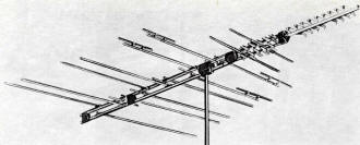
"Nothing," Mac replied, "but these Quantum antennas by Channel Master represent
a new concept in TV antenna design, and I want to see if they're as good at noise
reduction as claimed."
"How can a TV antenna reduce noise?" Barney scoffed. "That's like saying the
windmills make the wind blow."
"Not true," Mac denied. "The IEEE defines noise as, 'unwanted disturbances superposed
upon a useful signal that tend to obscure its information content.' That's a very
broad definition and, as far as TV reception is concerned, includes interference
from such diverse sources as electrical ignition systems, all kinds of switches,
diathermy, X-ray, electronic ovens, universal motors, CB-amateur-police-taxicab
transmitters, FM broadcasts, static, power transmission lines, reflection ghosts,
and adjacent and co-channel interference. So an antenna that discriminates strongly
between a desired signal off the front and undesired noise off the sides or back
can have a marked effect on noise reduction. Such discrimination is achieved by:
(1) providing maximum antenna directivity, and (2) minimizing feedline pickup -
which, of course, degrades directivity."
 "You're right about the noise level coming
up all the time," Barney said. "We hams will testify to that. And it's getting tougher
and tougher to find a relatively quiet location for a radio telescope, like the
immense parabolic array at Green Bank, West Virginia. Scientists are already turning
to space to escape this 'ether pollution.' Noise is especially bad on channels 2
through 6. That's where you see the most - but not all - of the streaking, the herringbone
and moiré patterns, the venetian blind and windshield wiper effects, the shadowy
sync bars, etc. This condition is worst in the metropolitan areas, but it is getting
worse in the suburban areas, too, as the use of electrical appliances proliferates
and factories move out into the suburban and rural areas." "You're right about the noise level coming
up all the time," Barney said. "We hams will testify to that. And it's getting tougher
and tougher to find a relatively quiet location for a radio telescope, like the
immense parabolic array at Green Bank, West Virginia. Scientists are already turning
to space to escape this 'ether pollution.' Noise is especially bad on channels 2
through 6. That's where you see the most - but not all - of the streaking, the herringbone
and moiré patterns, the venetian blind and windshield wiper effects, the shadowy
sync bars, etc. This condition is worst in the metropolitan areas, but it is getting
worse in the suburban areas, too, as the use of electrical appliances proliferates
and factories move out into the suburban and rural areas."
"Glad to see you appreciate the problem," Mac commented. "Little can be done
if the source of interference is directly in line with the desired signal, but there's
at least a 50-50 chance the interference will come in off the sides or back of the
antenna. In the case of co-channel or adjacent channel, probably 90% of the undesired
signals come in from the rear because of the FCC's channel allocations. The set
owner should, therefore, without sacrificing gain, select an antenna designed for
high interference rejection.
"The Interference Rejection Factor of an antenna is defined as the ratio of the
antenna's maximum sensitivity (normally at the front) to its peak sensitivity in
the rear 180° sector. Note this is not, necessarily, the same thing as front-to-back
ratio. Quite often high gain antennas will have secondary lobes not directly opposite
the primary front lobe. Such an antenna may have a very high front-to-back ratio,
but the ratio of the front response to the response of say 30° either side of
the rear will be much lower.
"Up to now, according to Channel Master, the peak IRF of high gain antennas has
been 15 to 18 dB. This Quantum Model 1160 I am unpacking is claimed to have an IRF
of 35 dB. It is further claimed that, when the predominant interference originates
at the rear or sides of the antenna, an improvement of 10 dB in signal-to-noise
ratio will occur. This is equivalent to a 10 dB increase in antenna gain. In a deep
fringe area the elimination of interference by this high IRF can bring about the
same dramatic improvement you'd expect from a higher gain antenna. And in near-fringe
suburban areas, where you have enough TV signal but there are lots of interference
sources, the high IRF should usually eliminate all signs of interference."
"Sounds great, but how do they do it?" Barney said skeptically.
Mac had been busy unpacking the antenna and assembling it as he talked. This
did not take long because the elements snapped out and the boom sections were fastened
together with bolts and wing nuts.
"According to Channel Master, the extremely high IRF is achieved by the application
of the Fourier Transform Theory to TV antenna design. The way current distributes
over the elements of an antenna determines its gain, bandwidth, and pickup patterns.
In the past, uniform current distribution has been the key to high broadband gain;
but the Transform Theory, widely applied to radio telescopes and space communication,
states a tapered, symmetrical distribution of current over an antenna's elements
will yield patterns with the smallest side and rear lobes. As one CM engineer puts
it: 'Just as the amplitude function of a waveform is transformed into the frequency
spectrum, so the distribution of current over an antenna array is transformed into
the radiation pattern by the Fourier Transform.'"
"Until recently almost all work in this connection has been done on broadside
arrays of the parabolic and 'bed-spring' types. Very little application has been
attempted on end-fire Yagi-style arrays. One reason has been the lack of instrumentation
to measure accurately the amplitude and phase differences in the antenna elements.
But with the development about five years ago of the Hewlett-Packard Model 8405
Vector Voltmeter, which allows measurement of amplitude and phase differences of
two signals up to 1000 MHz, the roadblock was removed.
Experimental Development. "Even so, CM spent three years of
experimental effort to develop the Quantum line of antennas - work consisting of
painstaking adjustment of element configurations, lengths, and spacings, and testing,
testing, testing. When you consider that this top-of-the-line Model 1160 has 16
fed elements and 26 parasitic elements and that a change in anyone affects the others,
you get some idea of the enormity of the job."
"I still am not sure what you mean by 'tapered currents over the antenna elements.'
"
"Let me try to explain. First note that this antenna does not consist of a single
divided 'driven' element connected to the feed line and a bunch of solid parasitic
directors and reflectors. Instead the boom is divided lengthways into an upper and
lower section separated by heavy-duty insulating blocks to provide a modified truss
construction. Each fed element is cut in two in the middle and has one half connected
to the top part of the boom and the other directly beneath to the lower half. Since
the feedline is connected to the two parts of the boom, that means all divided elements
connect to this line.
"Now if we measure the currents in these elements in the presence of a signal,
we find not all elements carry significant current at all frequencies. By proper
design we can produce currents that gradually increase as we go down the elements
and then fall off to produce a curve that satisfies the Fourier Transform Theory.
From one channel to another, the peak of this tapered current may fall on different
fed elements, but we must maintain the tapered distribution that provides the maximum
IRF. You will find more about this in Antennas by J. D. Kraus (McGraw-Hill 1950).
And in Microwave Antenna Theory and Design by S. Silver (McGraw-Hill 1950). And
when it is crystal clear to you, I wish you'd explain it to me!"
"Don't hold your breath," Barney warned, grinning. "I notice you speak of a 'Quantum
Line' of antennas. I take it CM makes several using this principle."
"That's right. They market fifteen different models designed to fit all receiving
conditions from the near suburban to the deepest fringe areas. The set owner can
order an antenna fitted to his needs as far as uhf, vhf, and FM reception in his
area is concerned - which brings up another point: with FM stations springing up
all over the place, FM interference with TV reception is an increasing problem.
So the Quantum, designed to furnish excellent FM reception normally, provides for
FM trapping if you need it. An optional FM trap that can be installed in the weatherproof
terminal housing located between the boom elements gives 20-dB attenuation of FM
signals without affecting the IRF of the antenna. Another feature is this front-end
section that looks like a sawfish's snout. It's actually a tunable uhf sector adjustable
for peak reception of the uhf channels."
"How is feedline pickup prevented with this antenna?"
"First, the antenna is electrically balanced. By connecting the right-hand sides
of the split elements alternately to the top and bottom portions of the boom we
achieve transposition in the feed. Also note these controlled-impedance transmission
rods that run from the feed points to the weatherproof plastic terminal housing.
And see how the boom is insulated from the mast? But even though the antenna itself
is carefully balanced, the receiver input may be unbalanced, in which case the feedline
will still pick up interference. In that event you may want to employ shielded coaxial
cable, and there is an optional balun transformer designed to fit into the terminal
housing."
"Those engineers seem to have thought of everything," Barney commented.
"Well, this antenna is certainly a far cry from the first two-element TV antenna
I ever saw. Personally, I'm delighted to see serious engineering going into TV antennas
by several manufacturers. Optimum TV reception is impossible without a good antenna.
I want to get this antenna up on the roof so we'll have a signal to check on cable
performance when we need it. You know how that goes. If we have good reason to suspect
the CATV signal is not up to par and call Fred, the manager, he reacts as though
you doubted his virtue."
"Yeah, I know," Barney agreed with a chuckle. "He is either seeing a perfect
picture down there in his office, or something must be wrong with the TV transmitter.
Nothing is ever wrong with the cable. He feels so sure of this there is no point
in sending a technician out to check. But if we can get a perfect picture off the
antenna and a lousy picture off the cable, we can make old Fred sweat."
Posted March 22, 2024
(updated from original post
on 9/6/2017)
Mac's Radio Service Shop Episodes on RF Cafe
This series of instructive
technodrama™ stories was the brainchild of none other than John T.
Frye, creator of the Carl and Jerry series that ran in
Popular Electronics for many years. "Mac's Radio Service Shop" began life
in April 1948 in Radio News
magazine (which later became Radio & Television News, then
Electronics
World), and changed its name to simply "Mac's Service Shop" until the final
episode was published in a 1977
Popular Electronics magazine. "Mac" is electronics repair shop owner Mac
McGregor, and Barney Jameson his his eager, if not somewhat naive, technician assistant.
"Lessons" are taught in story format with dialogs between Mac and Barney.
|